What do you need?
Niko requirements
Your Niko Home Control installation meets the following requirements:
-
It has a connected controller II.
-
It is configured with the most recent programming software.
You need to install the following additional products:
You will obtain the best results if you connect both the fans and the valves of your system. However, you can also connect either one.
|
|
Required additional product |
Reference number |
|---|---|---|
|
Fan control |
Analogue control module(s) |
|
|
Valve control |
Heating or cooling module(s) Switching module (in some cases*) |
|
|
Thermostat (one per zone) |
|
The amount of modules that you need depends on the properties of your system. Consult the wiring diagrams to fully understand the requirements.
You need:
-
one free output contact on the analogue control module(s) for each zone equipped with a fan coil unit that you want to connect
-
one free output contact on the heating or cooling module(s) for each zone equipped with a thermal actuator valve that you want to connect
-
one or two free contacts to connect to the heat pump (check the requirements and wiring diagrams of your specific heat pump):
-
one to signal heating/cooling demand
-
one to signal heating/cooling selector (only needed if your heat pump is capable to provide both warm and cool water)
-
*For example, in a configuration with two zones for heating and cooling, you will use one heating or cooling module which has up to four HVAC contacts.
Jaga requirements
Your system meets the following requirements:
-
It is a fan coil unit, that contains a water loop and a fan.
-
Your device can be controlled via:
-
one thermal actuator valve for each zone
-
one 0–10 V contact for each zone
-
-
It is connected to a heating and/or cooling unit for hydronic applications, such as a heat pump, boiler, etc.
Also check the specific requirements for your water source (heat pump, boiler, etc.)
Your system is one of the following Jaga products*:
-
a Strada Hybrid or Clima Canal equipped with a Jaga Dynamic Product Controller.
-
a Briza
*Consult the website of the supplier for detailed specifications and the latest products.
Wiring diagrams
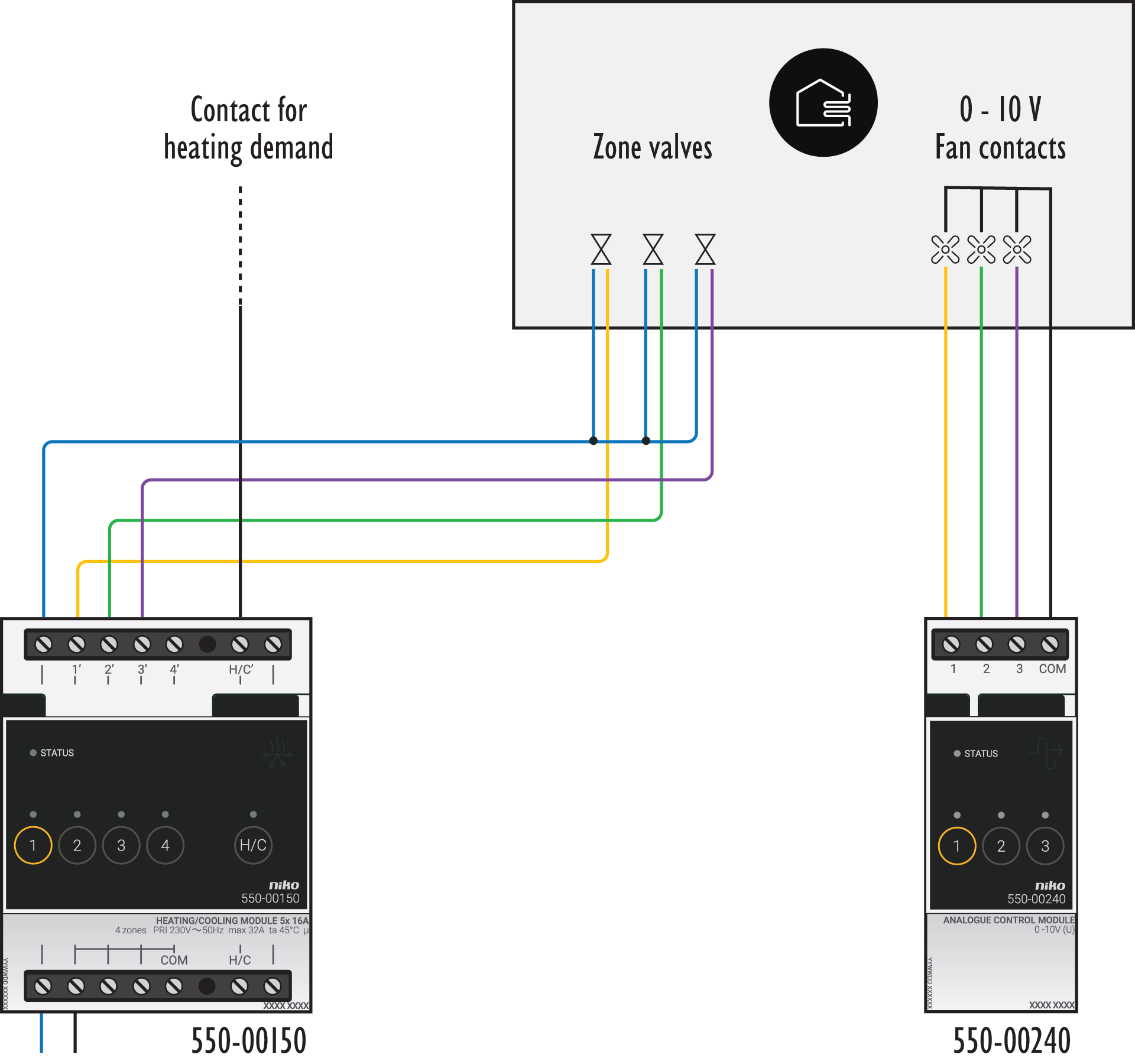
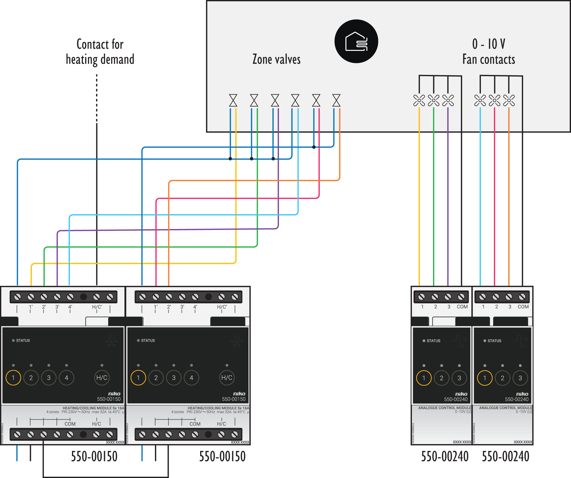
In case of a heating system:
|
3 zones |
6 zones |
|---|---|
|
|
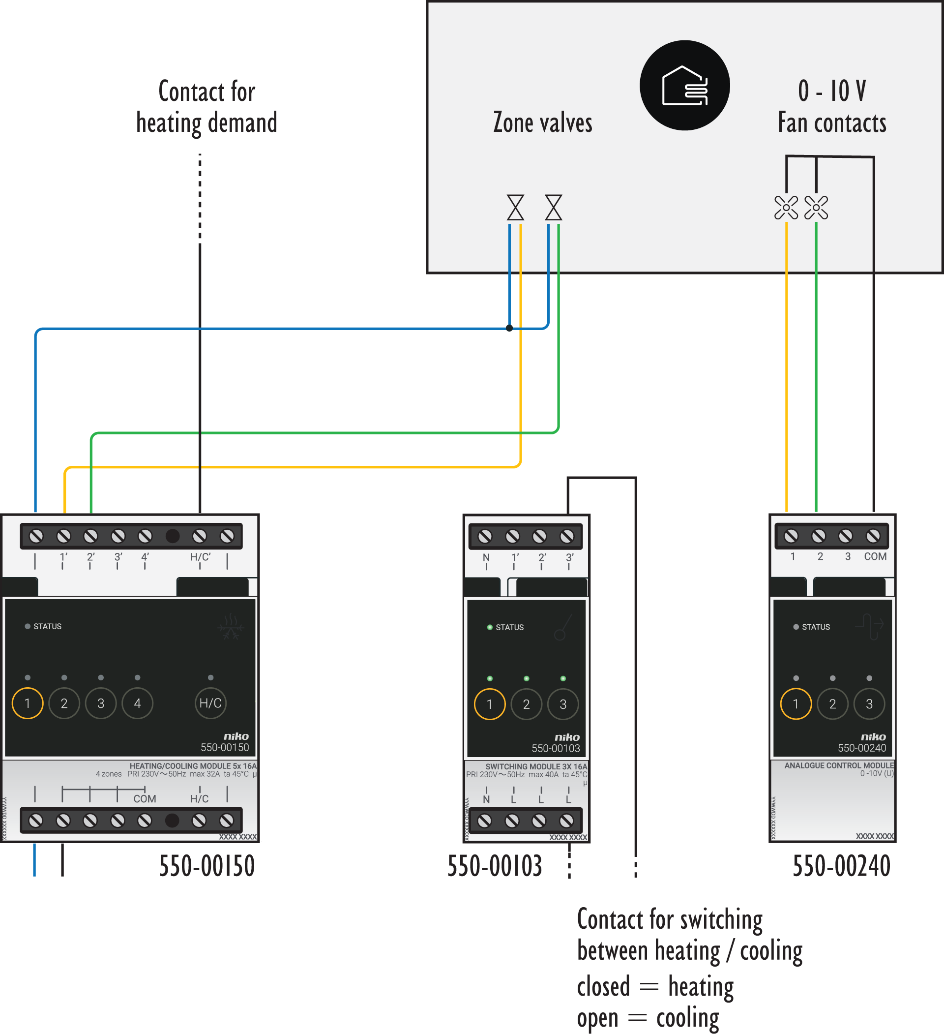
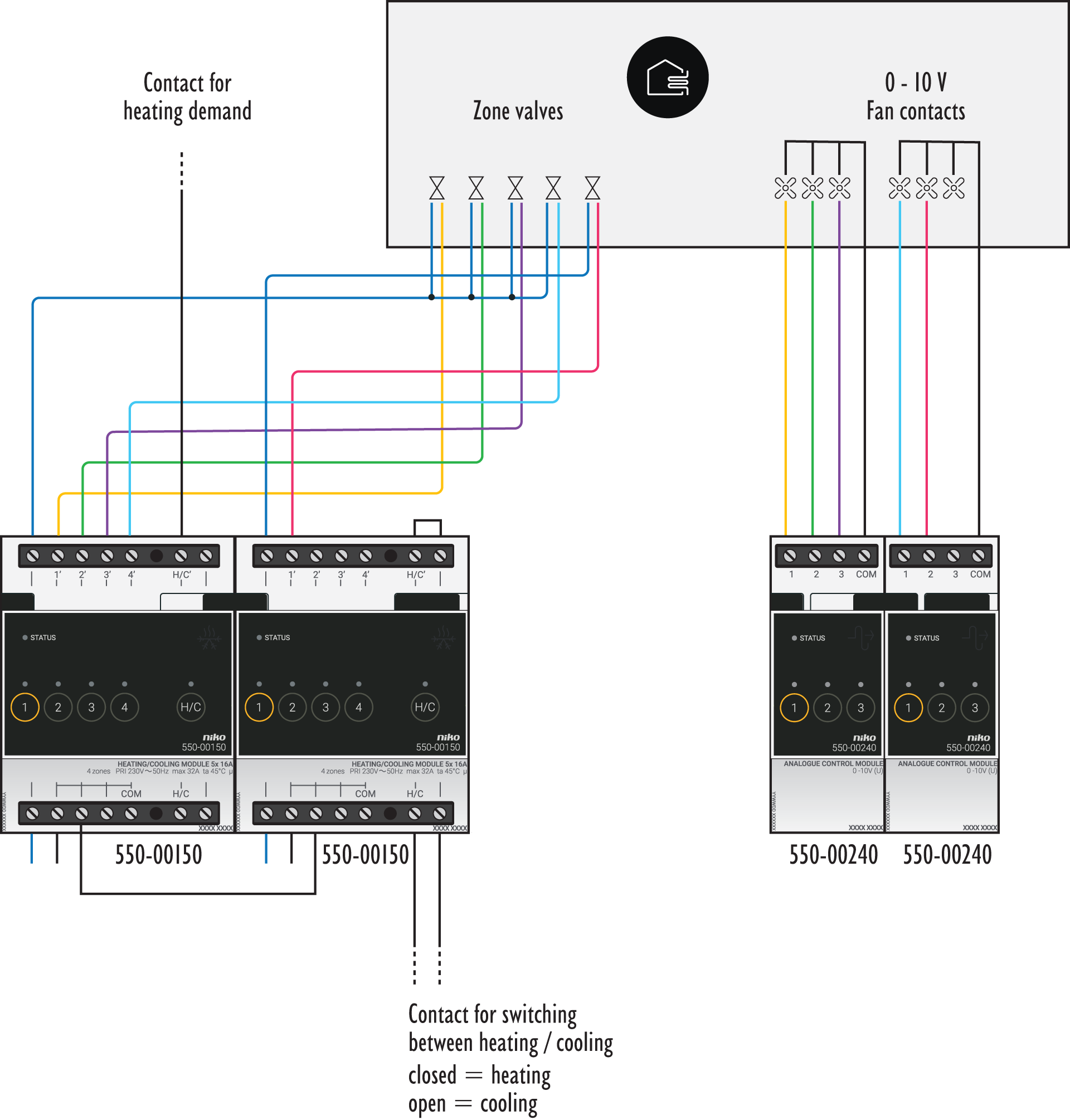
In case of a heating and cooling system:
|
2 zones |
5 zones |
|---|---|
|
|
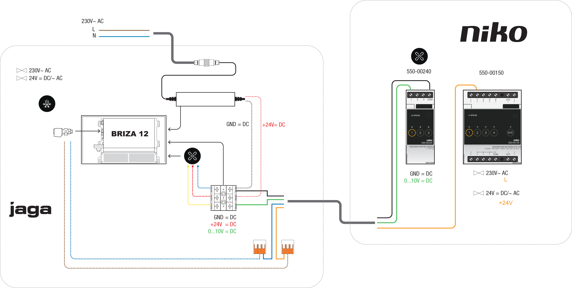
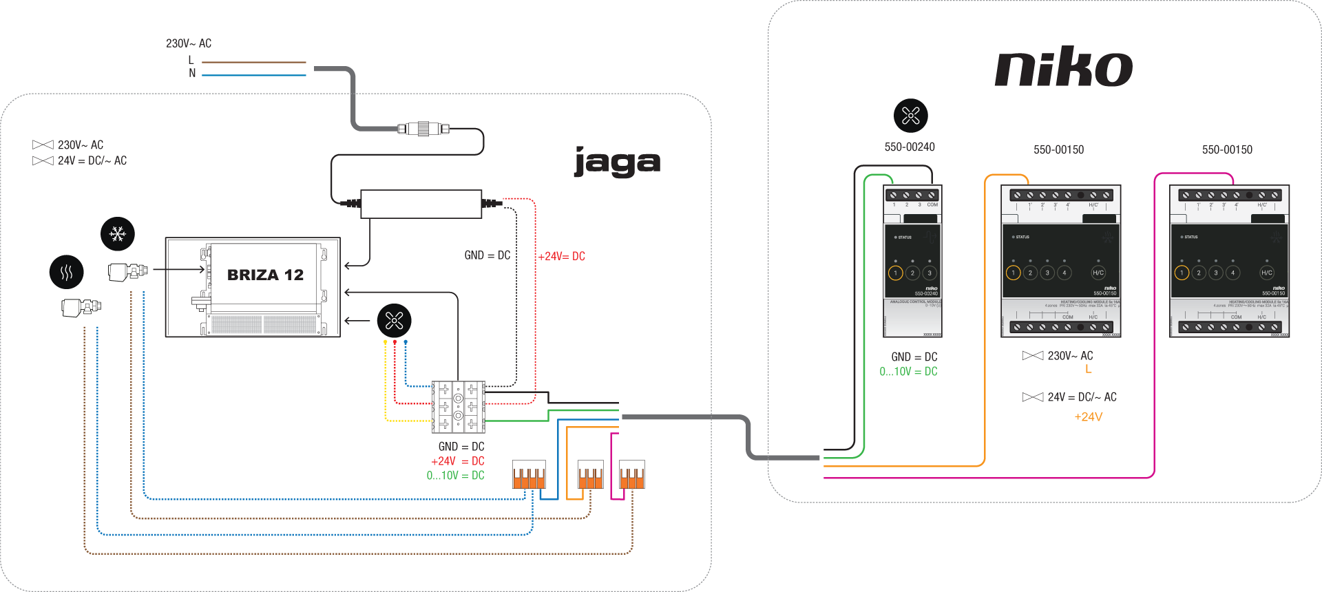
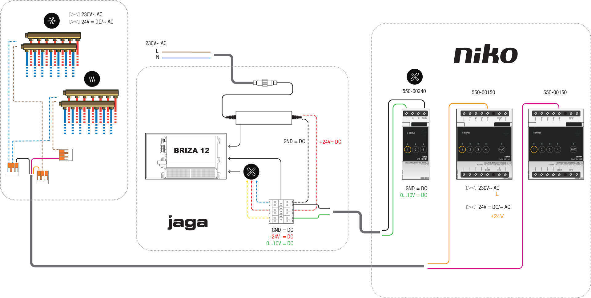
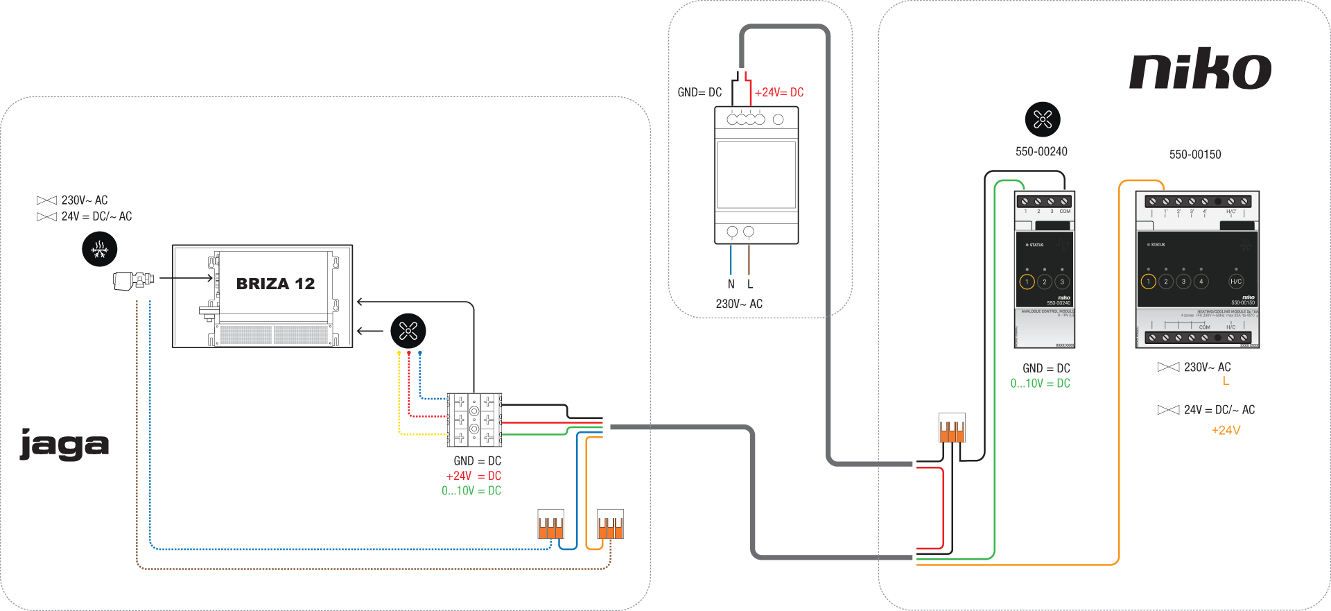
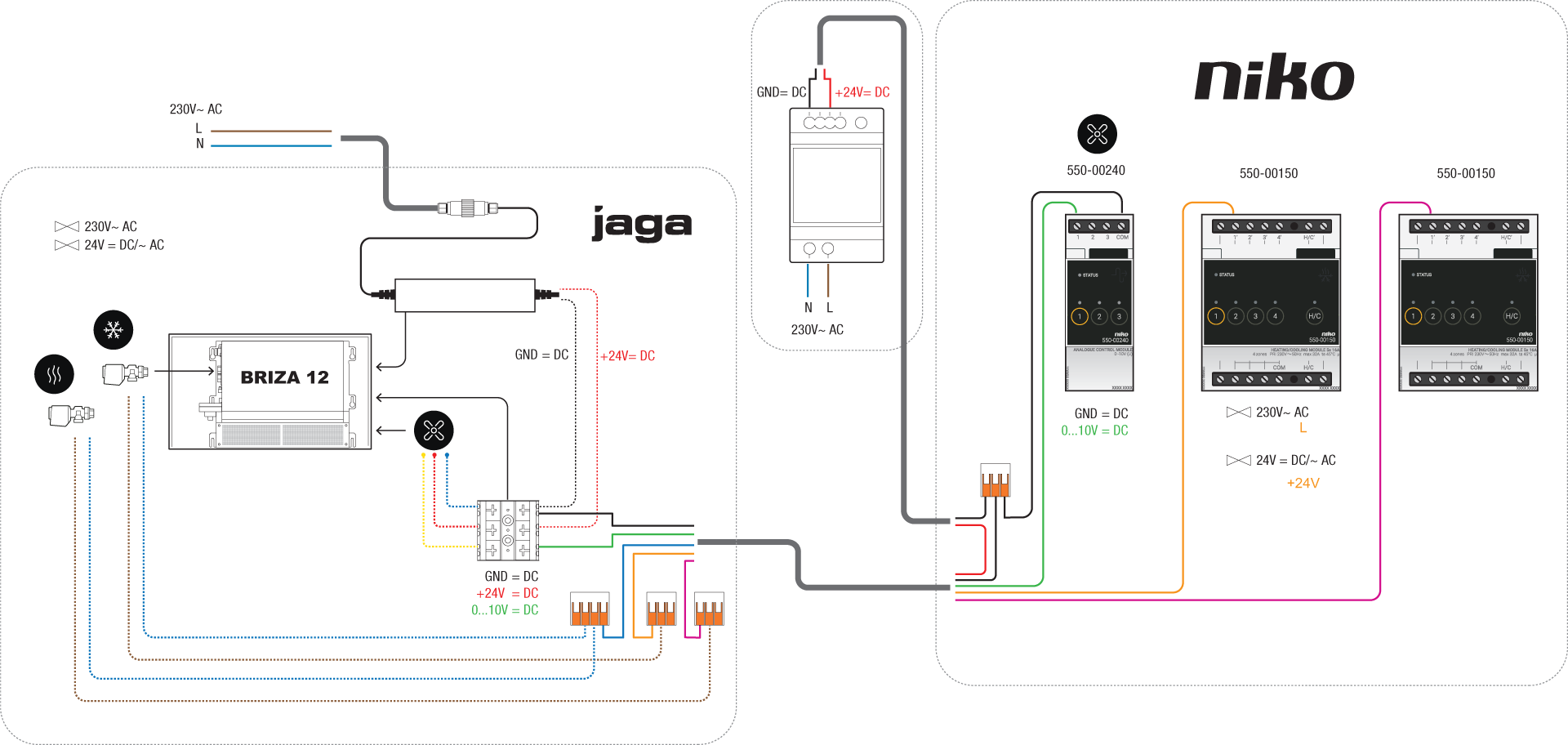
Wiring diagrams for Briza 12
|
Power supply located in |
Control of cold/hot water supply to the ventilo via |
2-pipe |
4-pipe |
|---|---|---|---|
|
Briza 12
|
a zone valve at the collector for cold/hot water |
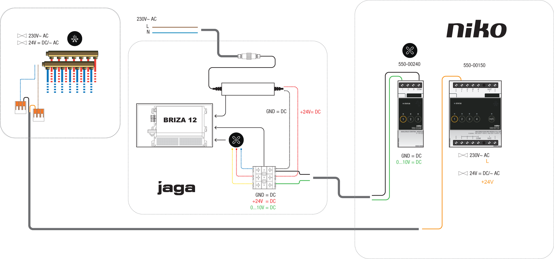
|

|
|
a valve at the ventilo collector |
|
|
|
|
electrical cabinet |
a zone valve at the collector for cold/hot water |
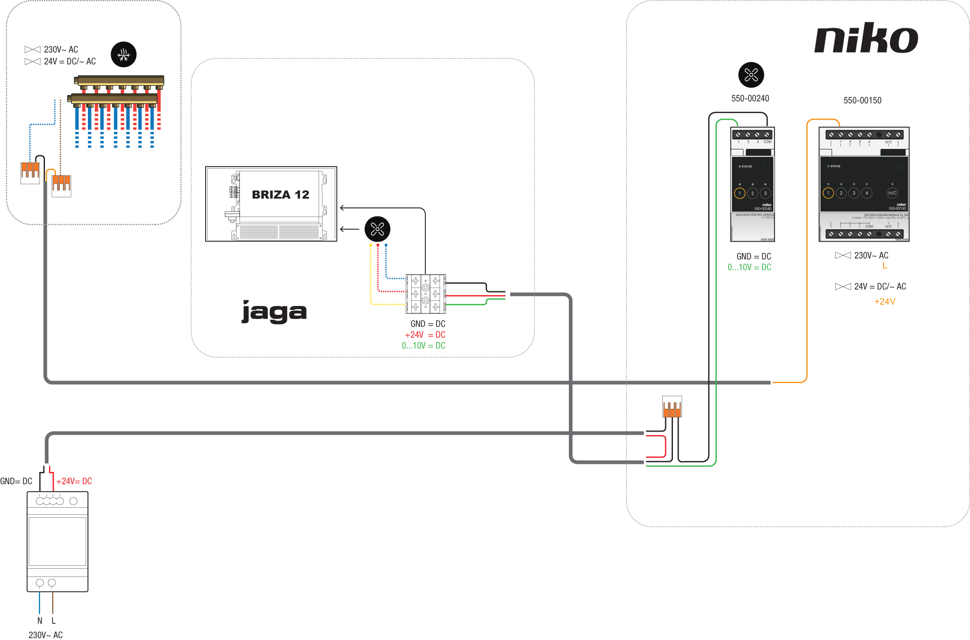
|
|
|
a valve at the ventilo collector |
|
|
Programming
Configure the analogue control module and/or heating or cooling module(s) in the programming software. Depending on the amount of zones, you can use the following programming examples as inspiration: