Use case
Your customer has one of the following Jaga radiator systems with 6 zones:
-
a Strada Hybrid or Clima Canal equipped with a Jaga Dynamic Product Controller or
-
a Briza
Each zone is equipped with a zone valve controlled by a thermostat.
When heating/cooling is required, your customer wants to control the speed of the ventilators mounted on the radiators with the Niko Home app:
-
low (30%)
-
medium (60%)
-
high (100%)
-
boost (100% for 15 min)
When heating/cooling is activated, the ventilator speed is set to 60% for heating and 100% for cooling.
When no heating is required, your customer cannot activate the ventilators.
You can also use push buttons with LED(s) and comfort sensors instead of thermostats, or a combination of both.
Procedure
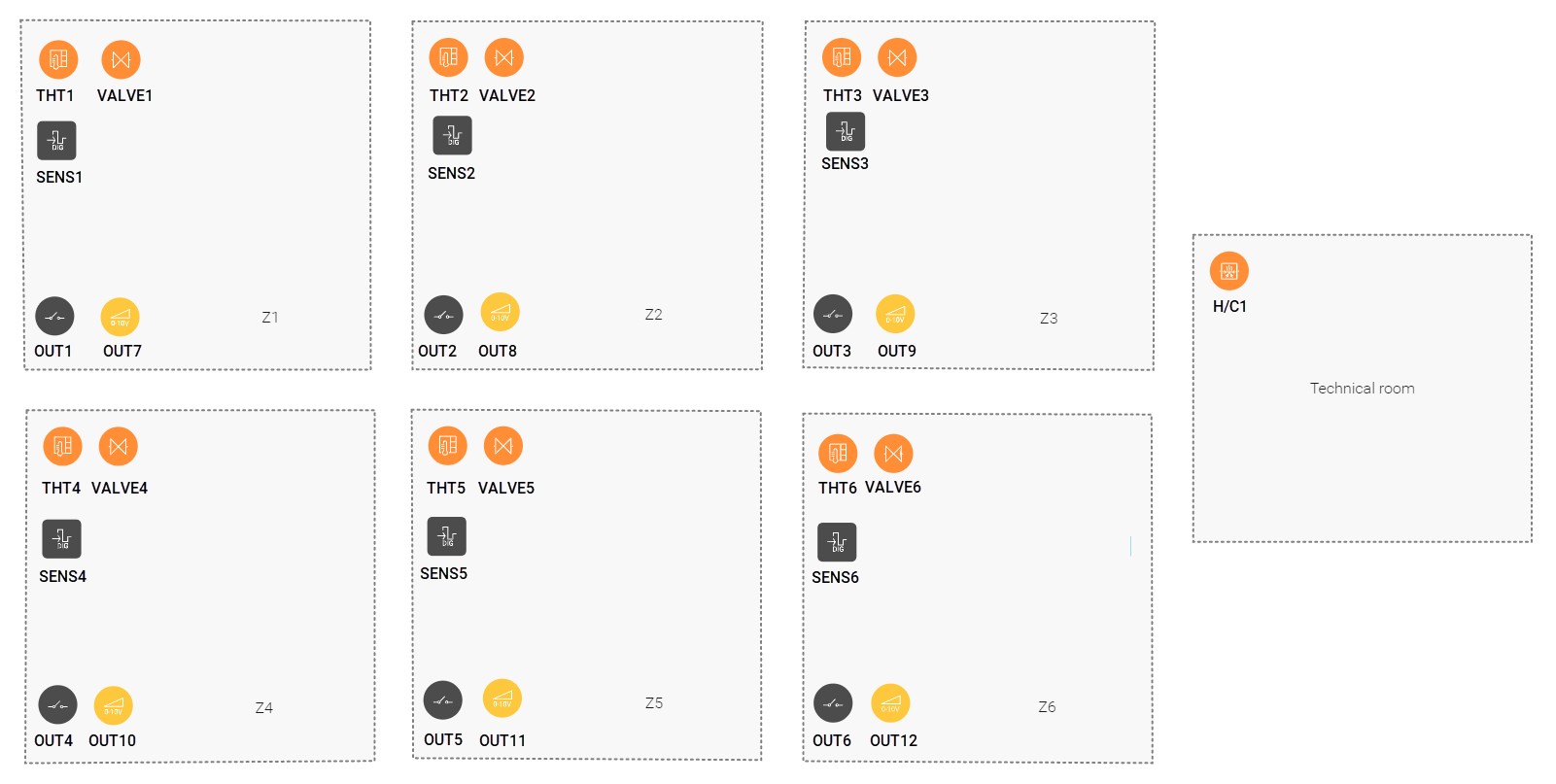
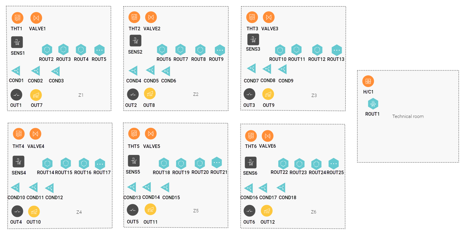
Creating the controls and the devices
-
Create the thermostats (THT1 to THT6).
-
Create the zone valves (VALVE1 to VALVE6).
-
Create a heating system (H/C1).
-
Create the digital sensors (SENS1 to SENS6) for heating/cooling requirement.
-
Create the other switched devices (OUT1 to OUT6) for controlling the 230 V to the zone valves.
-
Create the analogue outputs (OUT7 to OUT12) for controlling the fans.
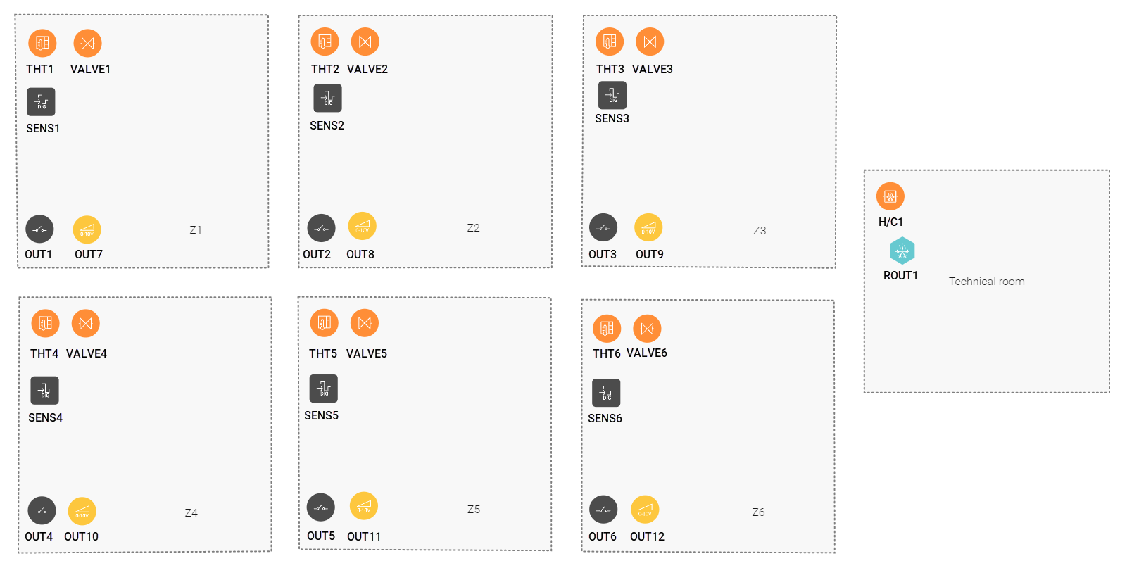
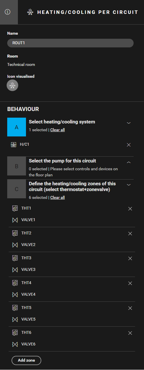
Creating the routine
Create a routine Heating/cooling per circuit (ROUT1). Use the following behaviour:
-
Select the heating system (H/C1).
-
Define the heating zones. Combine the correct thermostat with the corresponding zone valve (THT1 and VALVE1, THT2 and VALVE2,...).
-
(optional) Create notifications.
Creating the routines
In Z1,
-
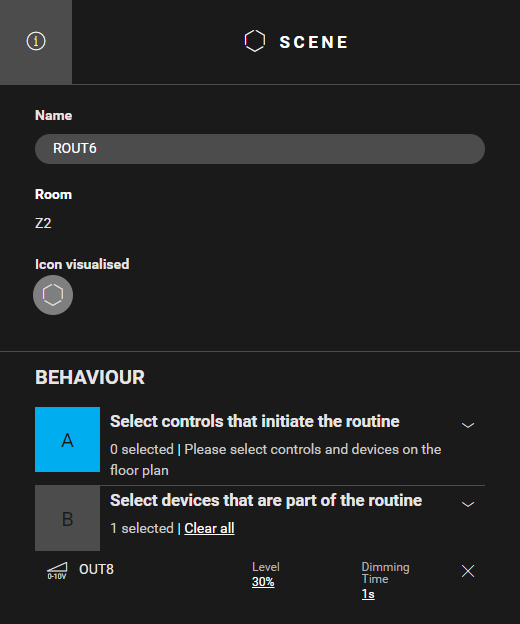
Create a routine Scene (ROUT2) to define the ventilation speed "low". Use the following behaviour:
-
Select the device that is part of the routine : analogue output OUT7
-
Set the parameter level to 30%
-
-
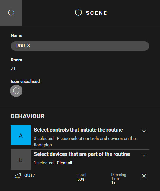
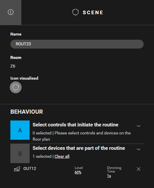
Create a routine Scene (ROUT3) to define the ventilation speed "medium". Use the following behaviour:
-
Select the device that is part of the routine: analogue output OUT7
-
Set the parameter level to 60%
-
-
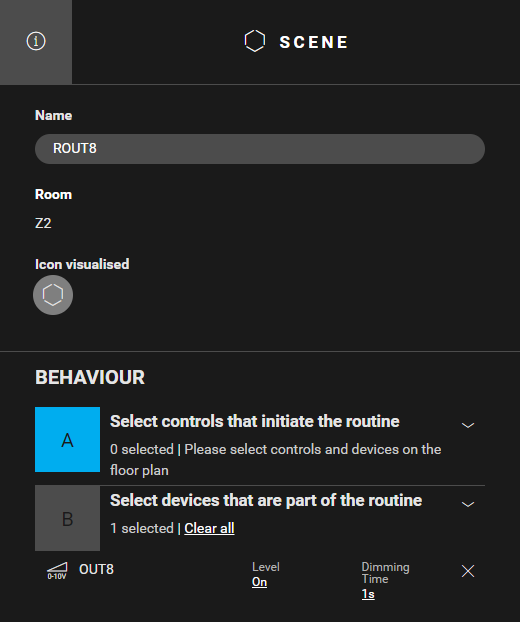
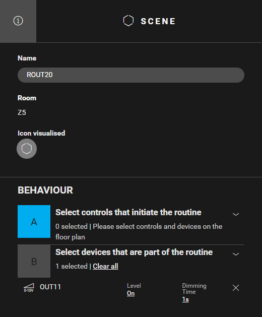
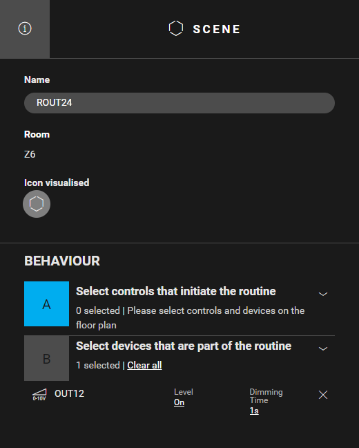
Create a routine Scene (ROUT4) to define the ventilation speed "high". Use the following behaviour:
-
Select the device that is part of the routine: analogue output OUT7
-
Set the parameter level to On
-
-
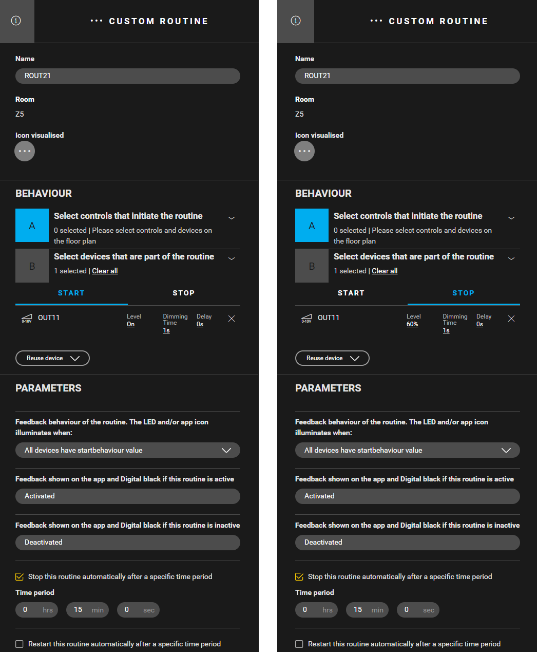
Create a routine Custom routine (ROUT5) to define the ventilation speed "boost". After 15 min the ventilation is set to "medium". Use the following behaviour:
-
Device that is part of the routine: analogue output OUT7
-
Start behaviour: OUT7: Level = On, Dimming Time = 1 s, Delay = 0 s
-
Stop behaviour: OUT7: Level = 60%, Dimming Time = 1 s, Delay = 0 s
-
Check "Stop this routine automatically..." and set the time period to 15 min
-
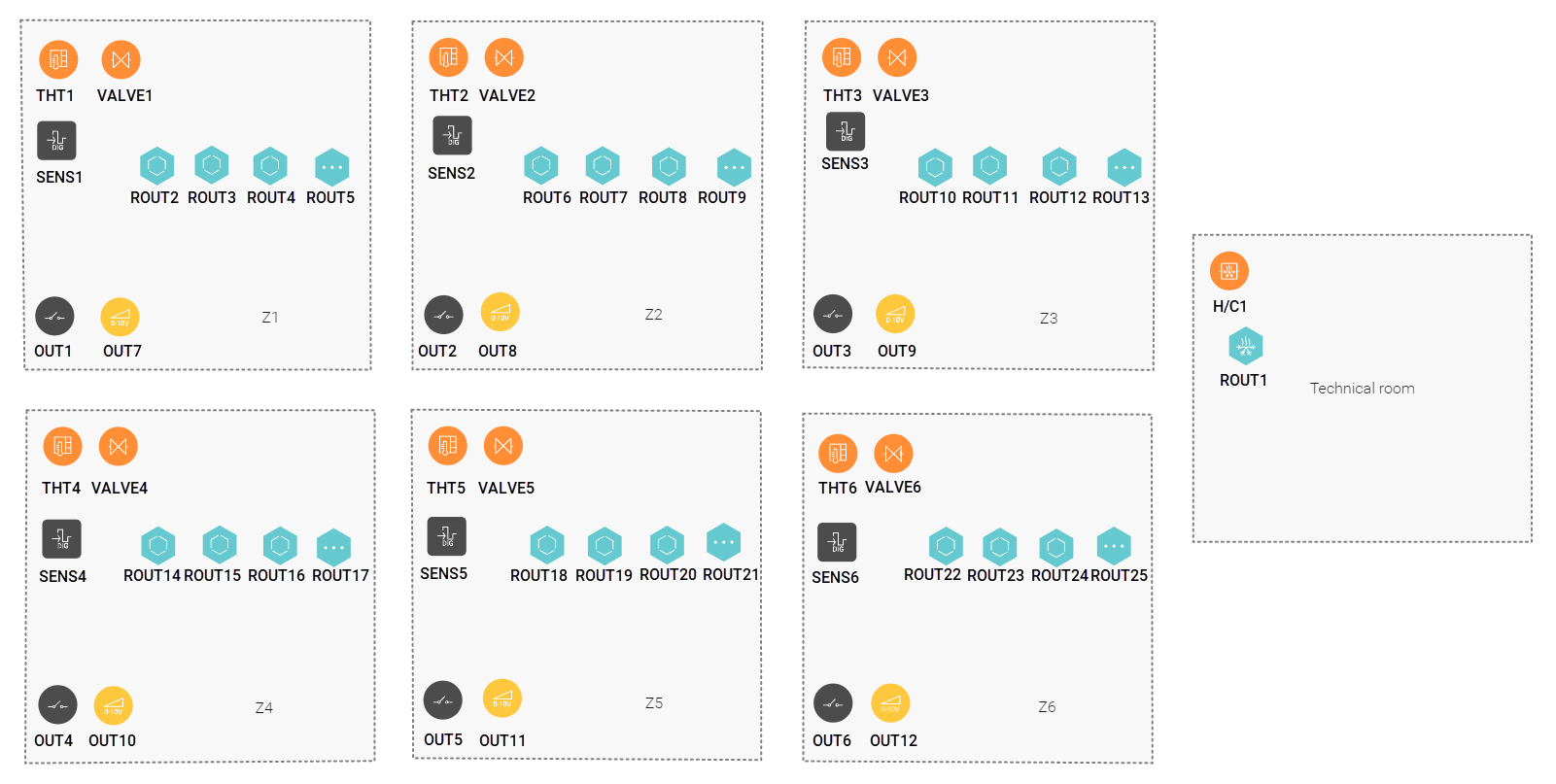
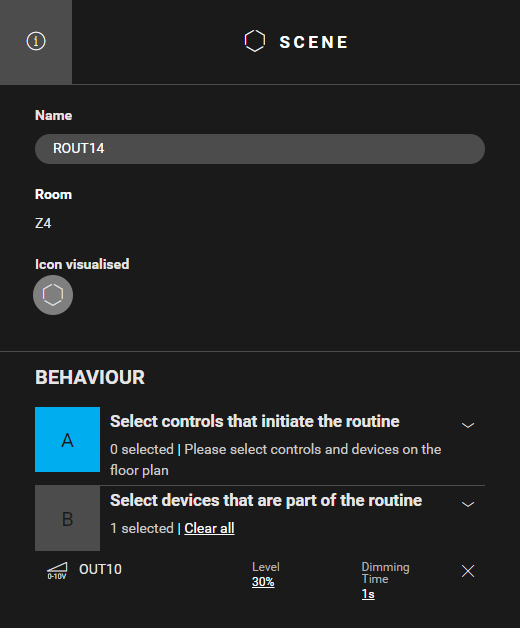
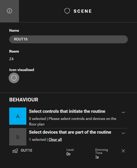
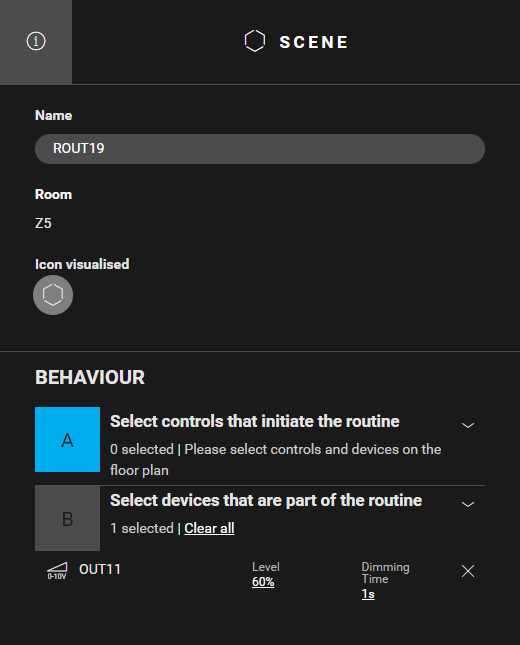
In Z2 to Z6 follow the steps described above but use the data in the table below.
Creating the conditions
If heating/cooling is required in a zone, then 230 V is applied to the zone valve, the fans are unlocked and the ventilation speed is set to 60% for heating and 100% for cooling.
If heating/cooling is no longer required in a zone, then 230 V is no longer applied to the zone valve, and the fans are locked and stopped.
In Z1,
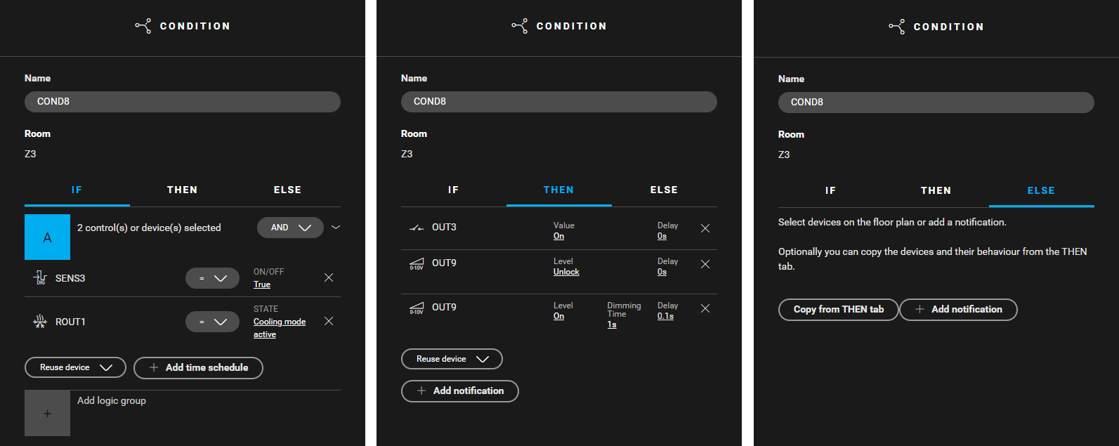
1. Create a condition (COND1) for controlling the fans when heating is required. Use the following logic:
-
IF SENS1= True AND ROUT1: State = Heating mode active
-
THEN
OUT1: Value = On, Delay = 0s
OUT7: Level = Unlock, Delay = 0 s
OUT7: Level = 60%, Dimming Time = 1 s, Delay = 0,1 s -
ELSE Leave empty
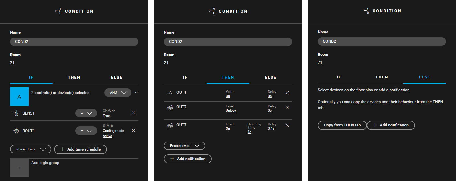
2. Create a condition (COND2) for controlling the fans when cooling is required. Use the following logic:
-
IF SENS1= True AND ROUT1: State = Cooling mode active
-
THEN
OUT1: Value = On, Delay = 0s
OUT7: Level = Unlock, Delay = 0 s
OUT7: Level = On, Dimming Time = 1 s, Delay = 0,1 s -
ELSE Leave empty
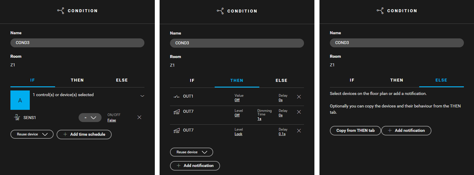
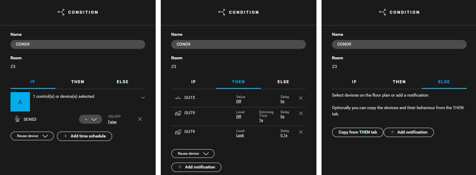
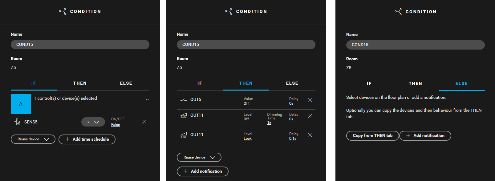
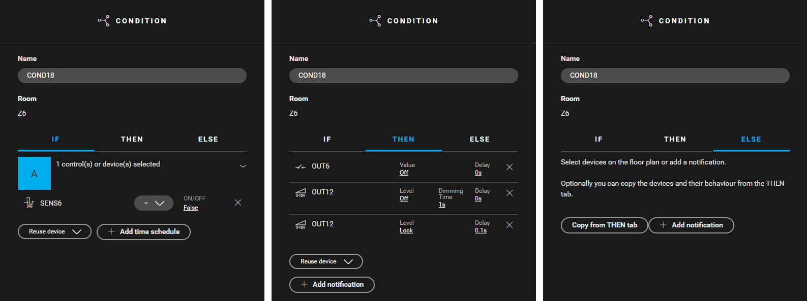
3. Create a condition (COND3) for controlling the fans when heating/cooling is no longer required. Use the following logic:
-
IF SENS1= False
-
THEN
OUT1: Value = Off, Delay = 0s
OUT7: Level = Off, Dimming Time = 1 s , Delay = 0 s
OUT7: Level =Lock , Delay = 0,1 s) -
ELSE Leave empty
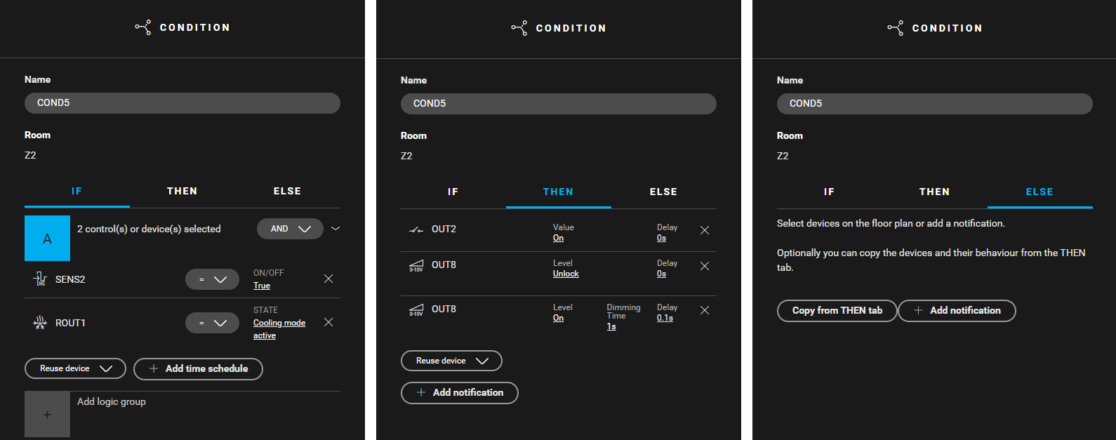
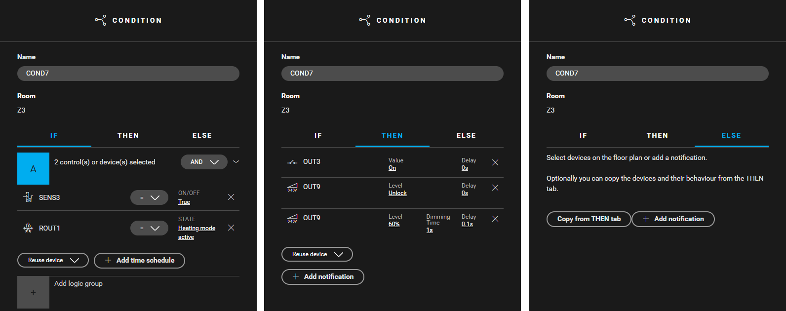
In Z2 to Z6 follow the steps described above but use the data in the table below.
|
In Z2 |
In Z3 |
In Z4 |
In Z5 |
In Z6 |
|---|---|---|---|---|
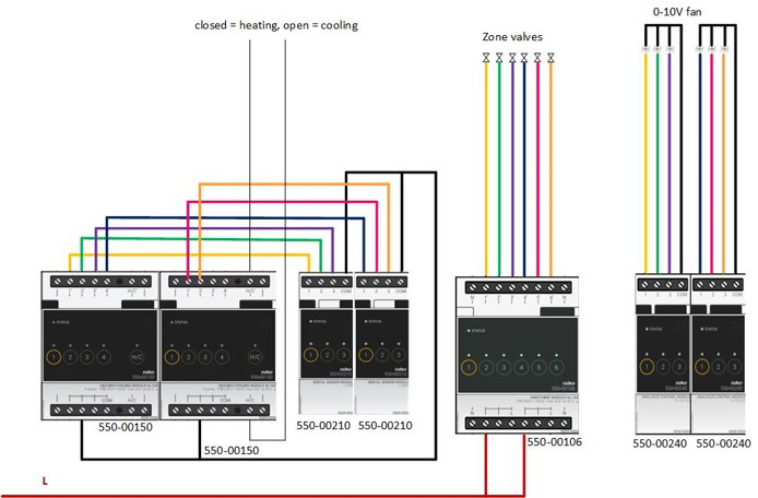
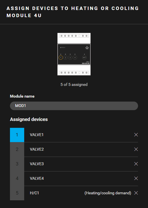
Filling the cabinet and addressing the devices
-
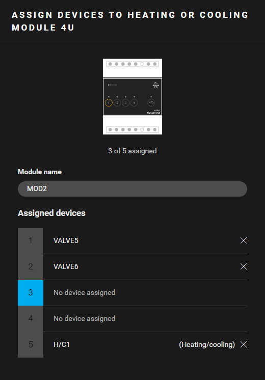
You can only address four zone valves to a heating or cooling module 4U. Contact 5 of the module is an H/C-contact.
-
Always address the heating/cooling system to the first heating or cooling module in the cabinet (contact 5).
|
Fill the cabinet with ... |
and address the following devices ... |
|---|---|
|
a heating or cooling module 4U (MOD1) |
|
|
a heating or cooling module 4U (MOD2) |
|
|
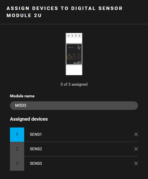
a digital sensor module 2U (MOD3) |
the digital sensors SENS1 to SENS3. |
|
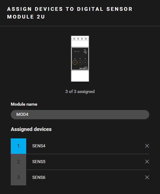
a digital sensor module 2U (MOD4) |
the digital sensors SENS4 to SENS6. |
|
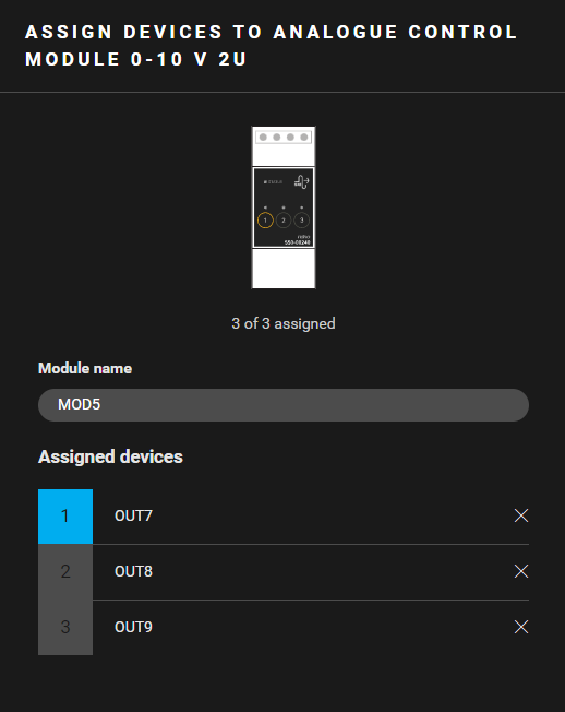
an analogue control module 0 - 10 V 2U (MOD5) |
the analog outputs OUT7 to OUT9. |
|
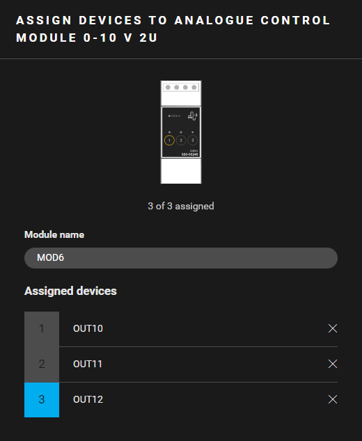
an analogue control module 0 - 10 V 2U (MOD6) |
the analog outputs OUT10 to OUT12. |
|
rail coupler (MOD7) |
/ |
|
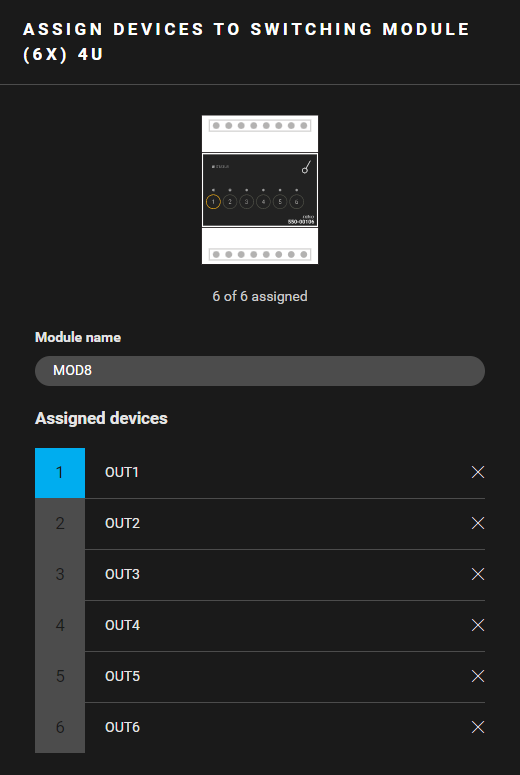
a switching module (6x) 4U (MOD8) |
the other switched devices OUT1 to OUT6. |


(*) This contact is not physically used in the installation. The contact closes when one of the thermostats demands heating and opens when they demand cooling.
(**) This contact is not physically used in the installation. You can address this contact also to another heating or cooling module.
Example
Click here to download the programming example.
(FPE_029_216_1.nhc2 file).
Wiring diagram