Use case
Your customer will use fan coil units to heat the rooms in the house.
In this example, we assume that 6 zones (rooms) have to be controlled.
In this example, there is 1 fan coil unit in each zone.
Each zone is equipped with a zone valve controlled by a thermostat.
When the zone thermostat requests heat, the fan of the fan coil unit will automatically be set to 60%.
When no heating is requested, the fan will automatically be deactivated.
Your customer wants to control the speed of the fan, mounted inside the fan coil units, manually using the Niko Home app:
-
low (30%)
-
medium (60%)
-
high (100%)
-
boost (100% for 15 minutes , then reduce to 60%)
As a thermostat, you can use a push buttons with LED(s) and comfort sensors or Digital black 24v.
This procedure is based on Niko Home Control programming software version 2.22 or more recent.
Procedure
Creating the controls and devices
-
Create the thermostats (THT1 to THT6).
-
Create the zone valves (VALVE1 to VALVE6).
-
Create a heating system (H/C1).
-
Create the analogue outputs (OUT1 to OUT6) for controlling the fans.

Creating the routine
Create a routine Heating/cooling per circuit (ROUT1). Use the following behaviour:
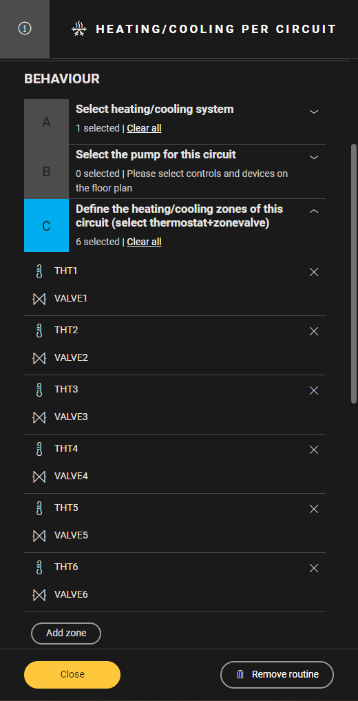
-
Select the heating system (H/C1).
-
Define the heating zones. Combine the correct thermostat with the corresponding zone valve (THT1 and VALVE1, THT2 and VALVE2, ...).

Creating the routines
In Z1,
-
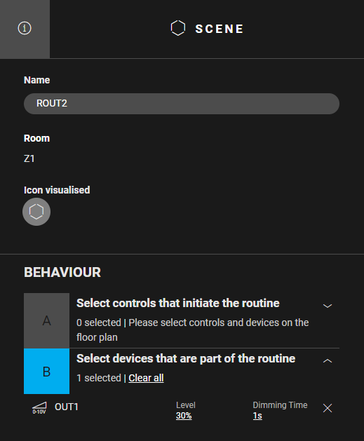
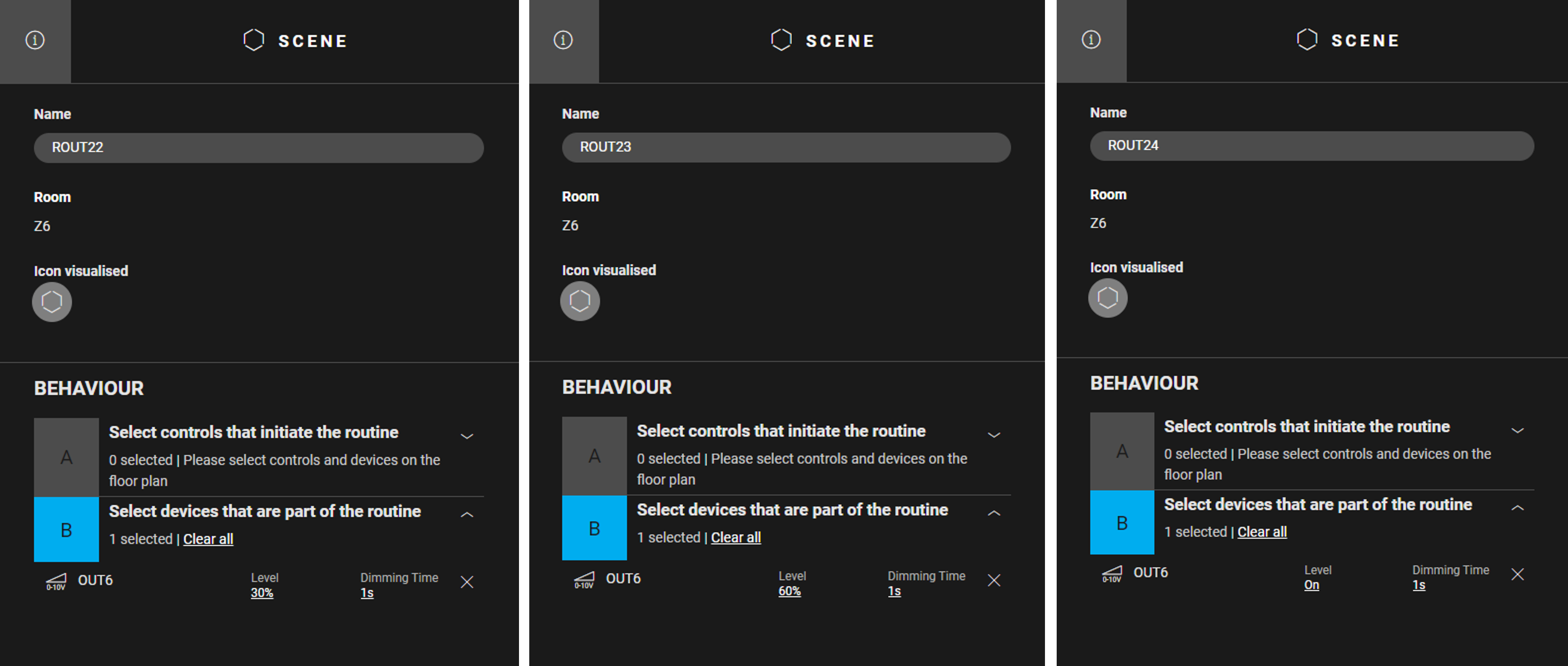
Create a routine Scene (ROUT2) to define the ventilation speed "low". Use the following behaviour:
-
Select the device that is part of the routine : analogue output OUT1
-
Set the parameter level to 30%
-
-
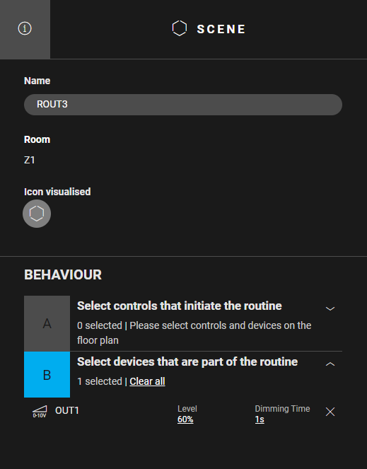
Create a routine Scene (ROUT3) to define the ventilation speed "medium". Use the following behaviour:
-
Select the device that is part of the routine: analogue output OUT1
-
Set the parameter level to 60%
-
-
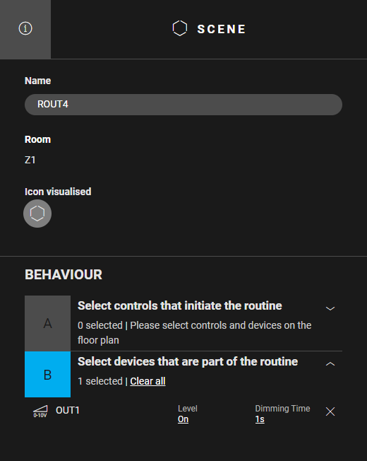
Create a routine Scene (ROUT4) to define the ventilation speed "high". Use the following behaviour:
-
Select the device that is part of the routine: analogue output OUT1
-
Set the parameter level to On
-
-
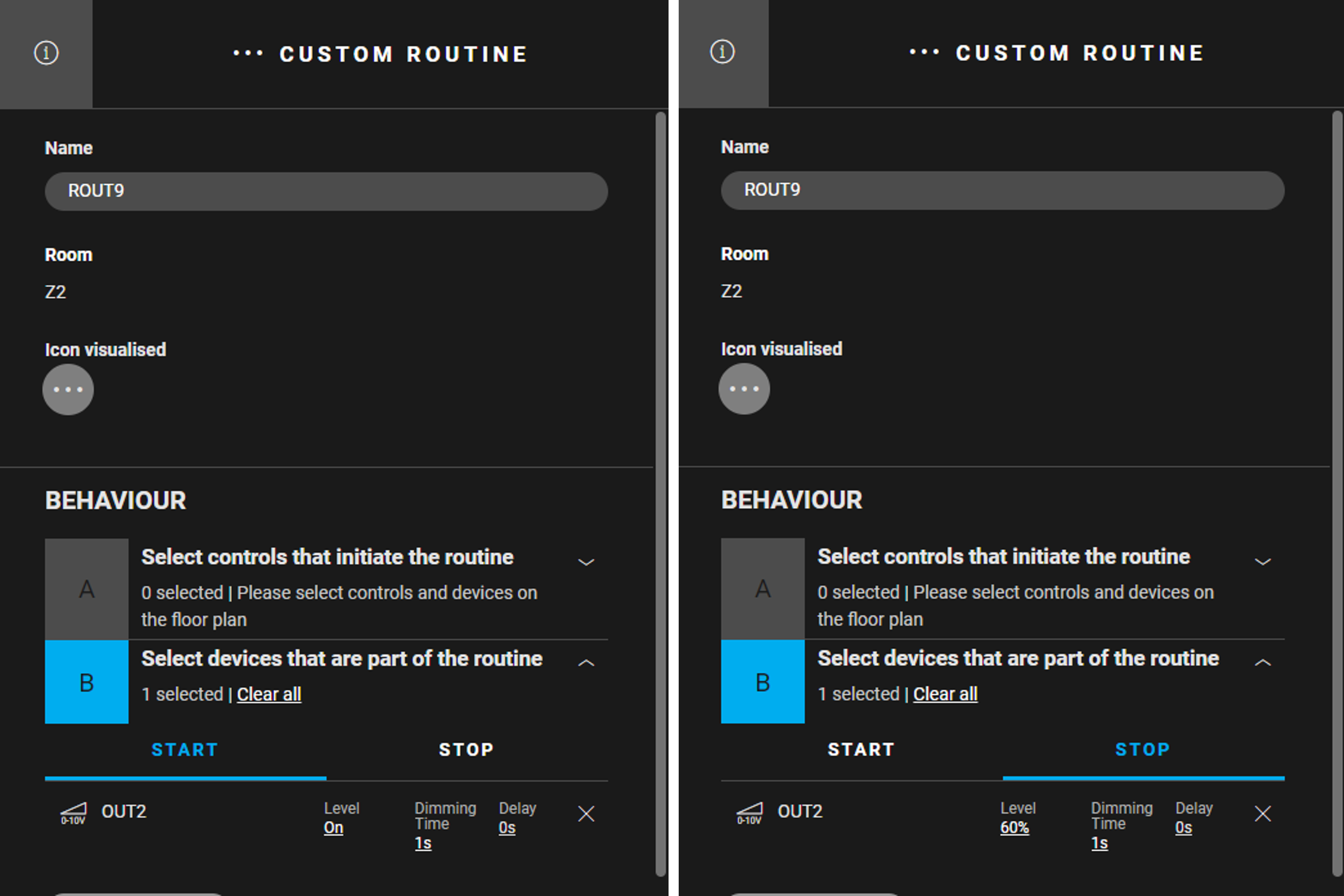
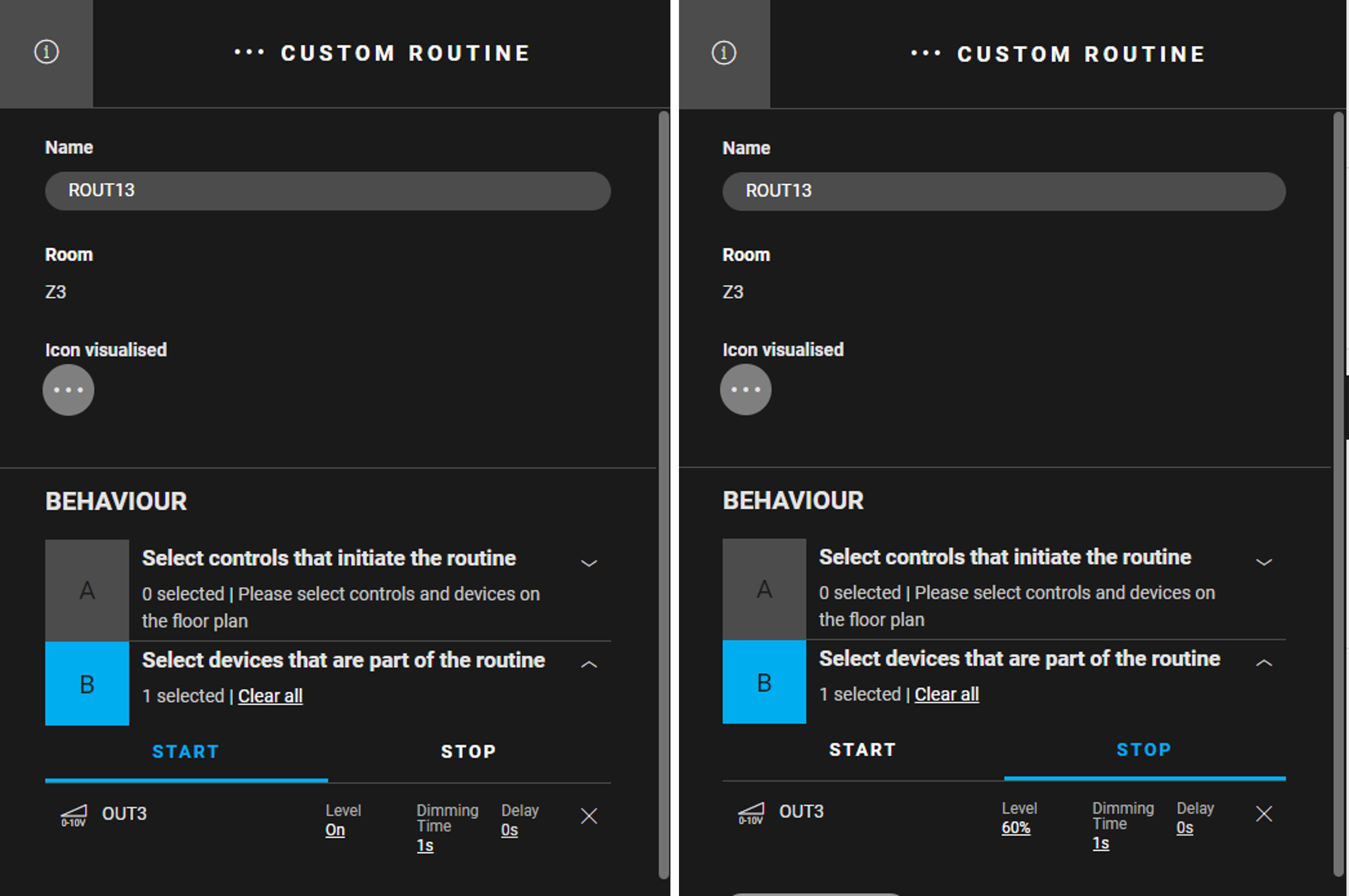
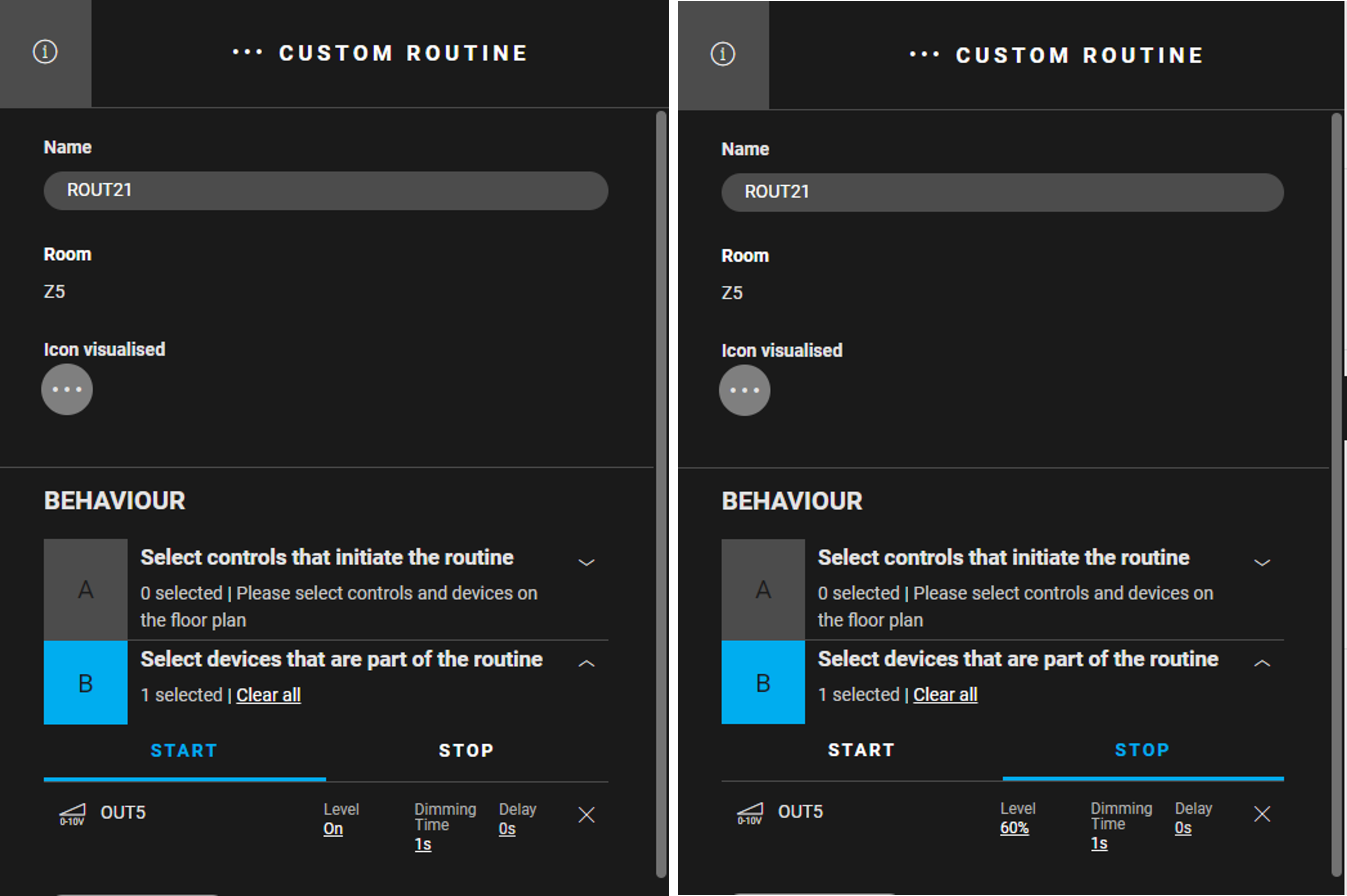
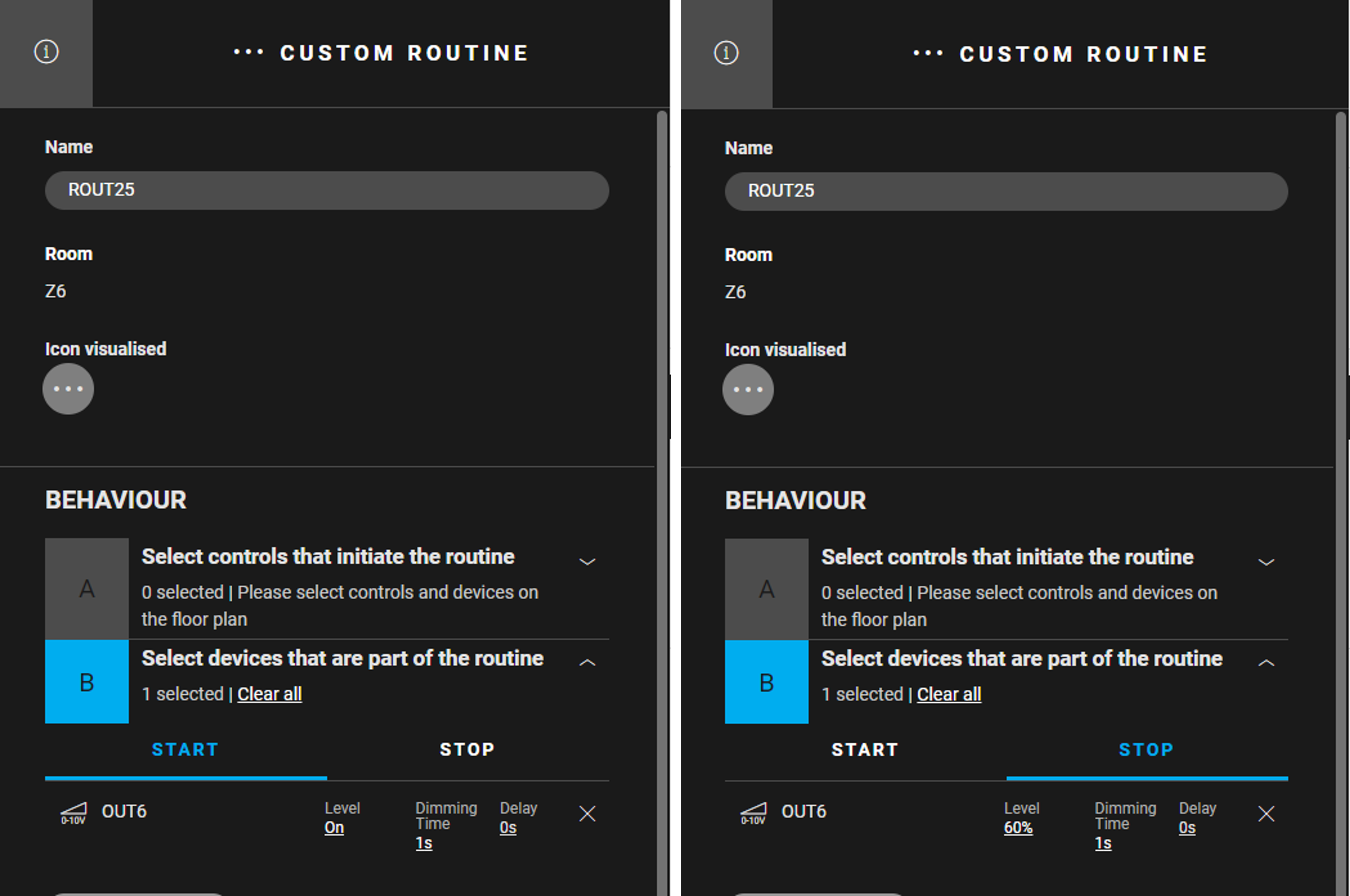
Create a routine Custom routine (ROUT5) to define the ventilation speed "boost". After 15 min the ventilation is set to "medium". Use the following behaviour:
-
Device that is part of the routine: analogue output OUT1
-
Start behaviour: OUT1: Level = On, Dimming Time = 1 s, Delay = 0 s
-
Stop behaviour: OUT1: Level = 60%, Dimming Time = 1 s, Delay = 0 s
-
Check "Stop this routine automatically..." and set the time period to 15 min
-

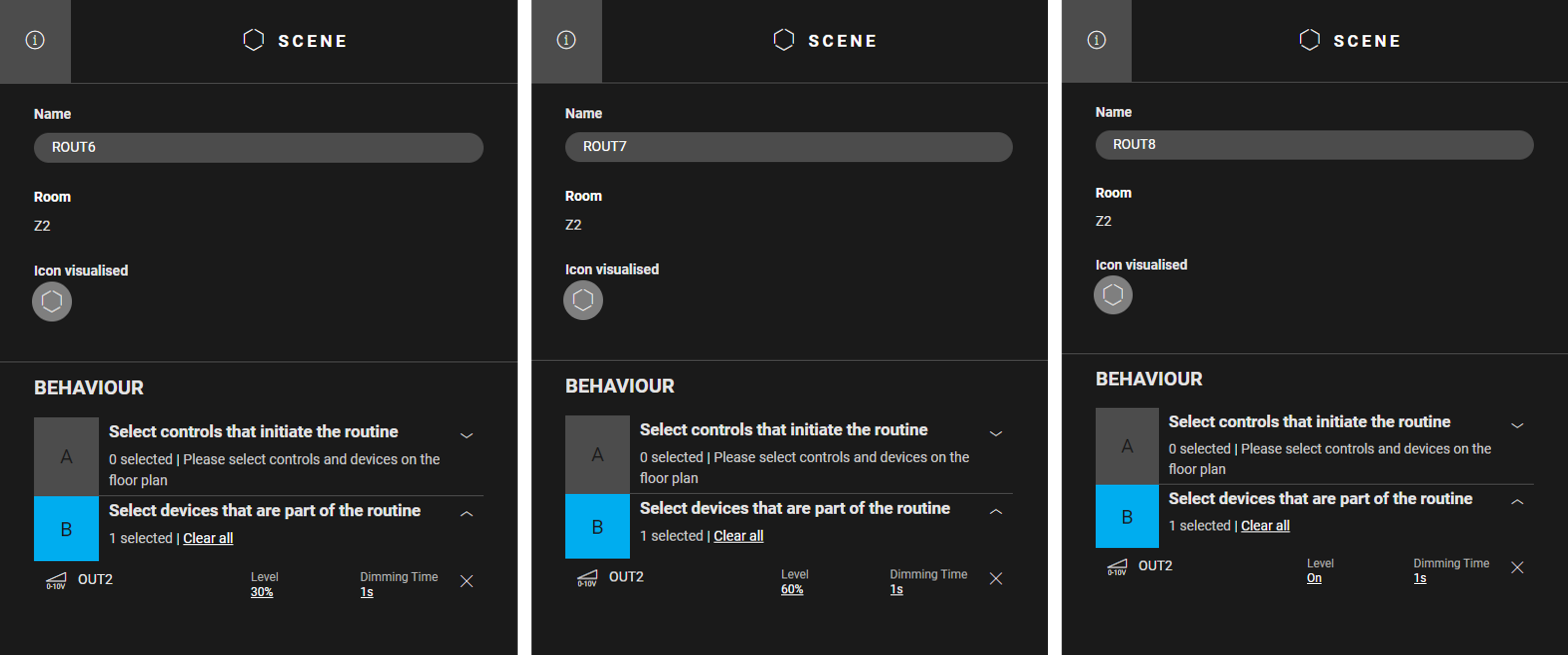
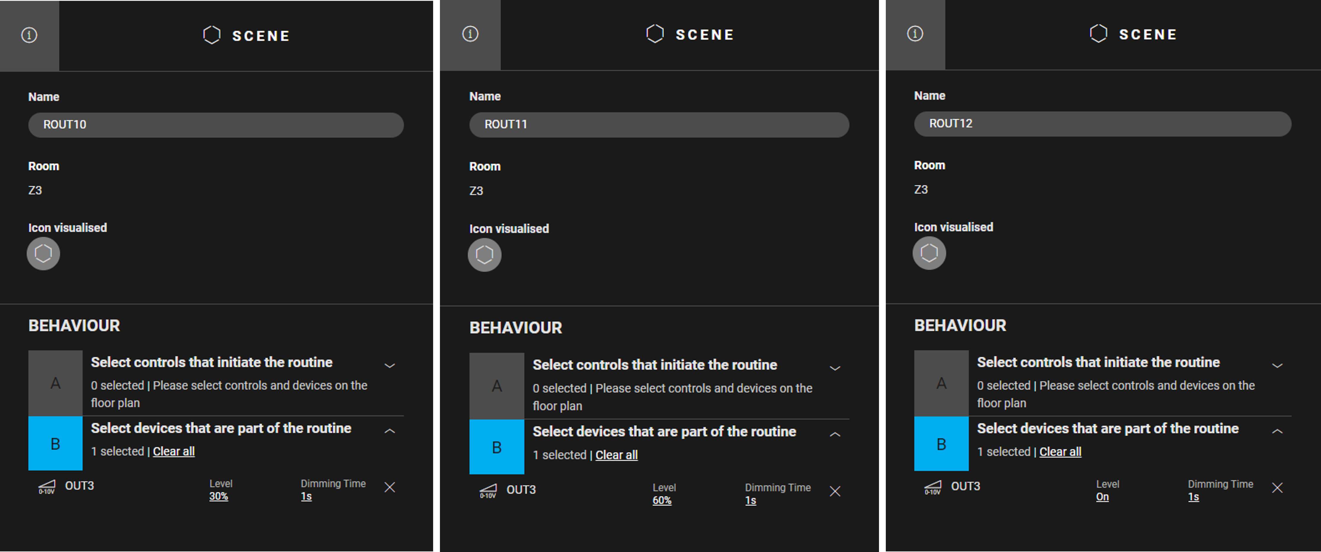
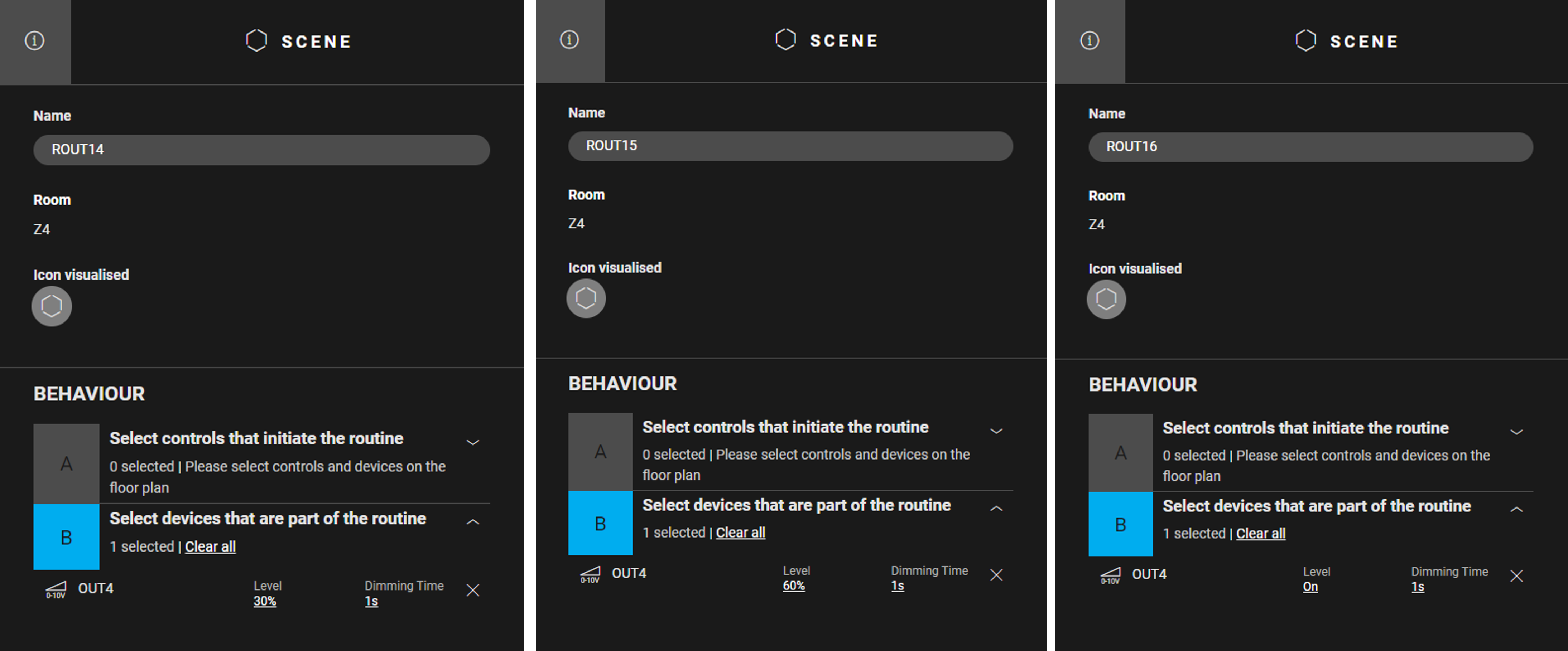
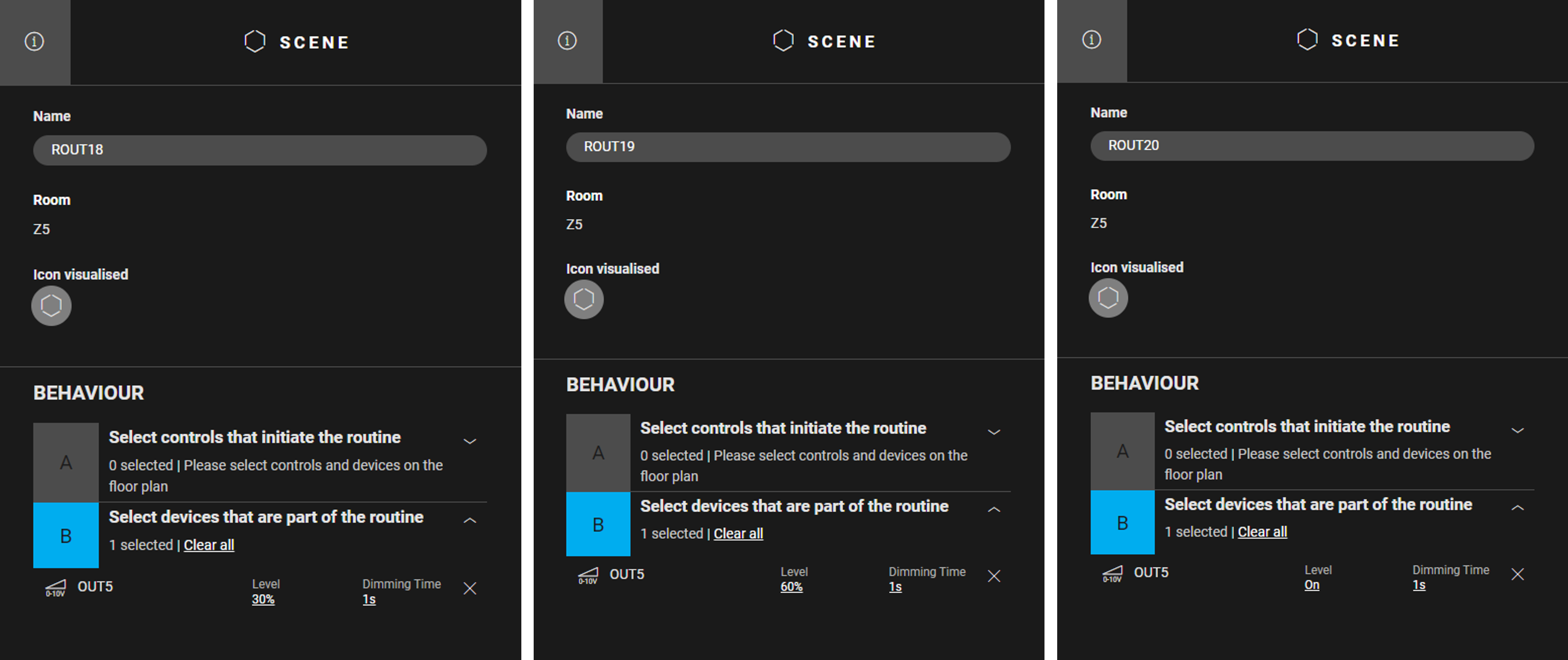
In Z2 to Z6 follow the steps described above but use the data in the table below.
|
Type of routine |
In Z2 |
In Z3 |
In Z4 |
In Z5 |
In Z6 |
|---|---|---|---|---|---|
|
Scene |
ROUT6, ROUT7 and ROUT8 with OUT2 |
ROUT10, ROUT11 and ROUT12 with OUT3 |
ROUT14, ROUT15 and ROUT16 with OUT4 |
ROUT18, ROUT19 and ROUT20 with OUT5 |
ROUT22, ROUT23 and ROUT24 with OUT6 |
|
Custom routine |
ROUT9 with OUT2 |
ROUT13 with OUT3 |
ROUT17 with OUT4 |
ROUT21 with OUT5 |
ROUT25 with OU |
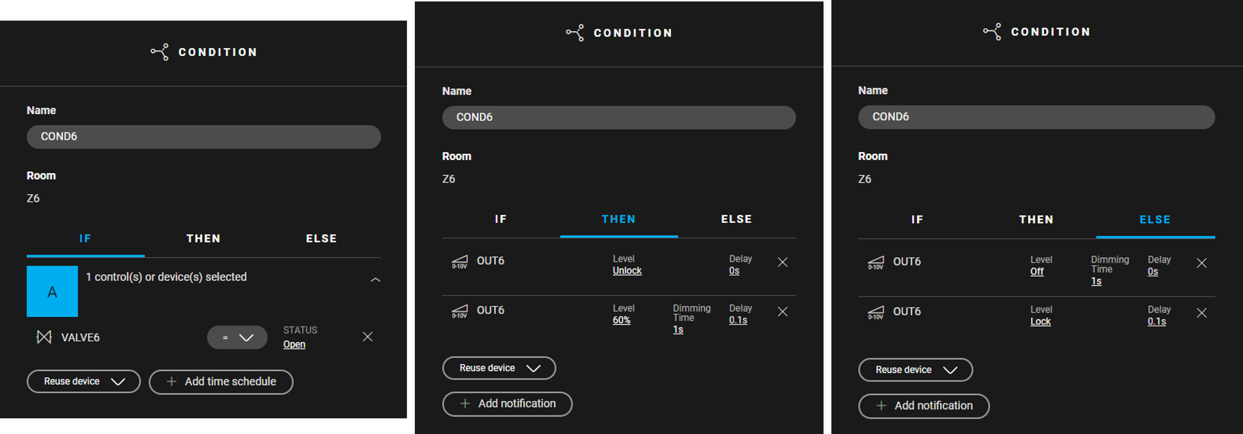
Create the conditions
If heating is required in a zone, then 230 V is applied to the zone valve, the fans are unlocked and the ventilation speed is set to 60%.
If heating is no longer required in a zone, then 230 V is no longer applied to the zone valve, and the fans are locked and stopped.
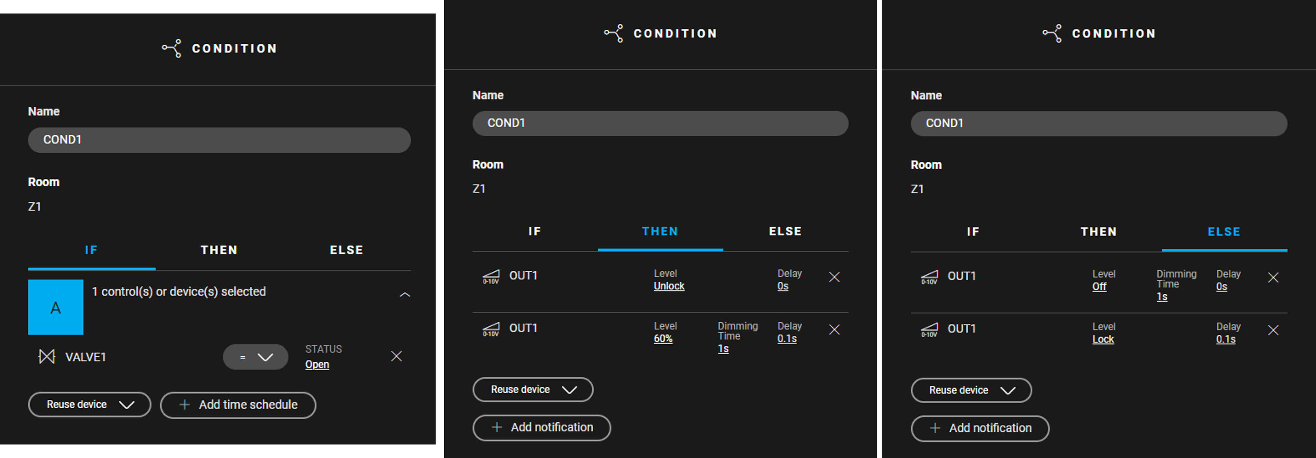
In Z1, create a condition (COND1) for controlling the fans. Use the following logic:
-
IF VALVE1= Open
-
THEN
OUT1: Level = Unlock, Delay = 0 s
OUT1: Level = 60%, Dimming Time = 1 s, Delay = 0,1 s -
ELSE
OUT1: Level = Off, Dimming Time = 1 s, Delay = 0 s
OUT1: Level = Lock, Delay = 0,1 s

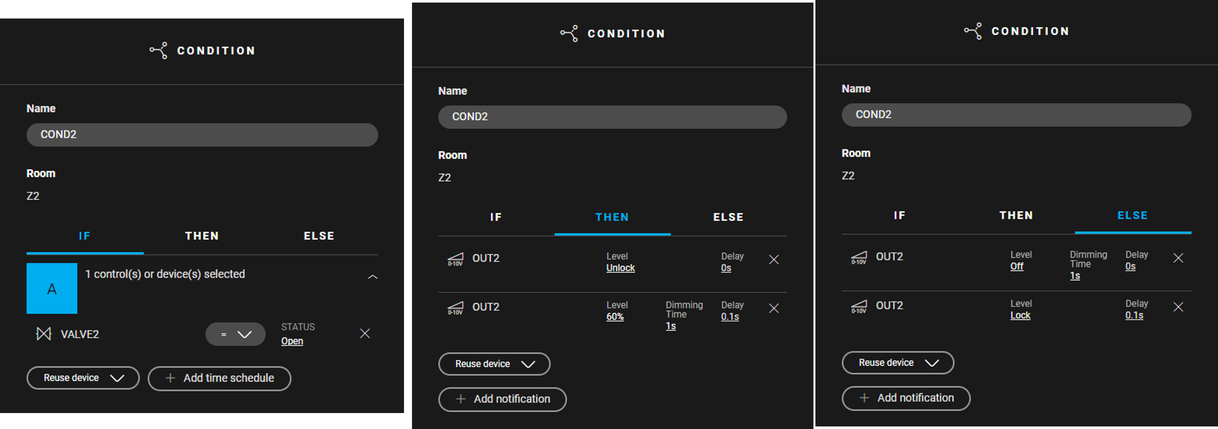
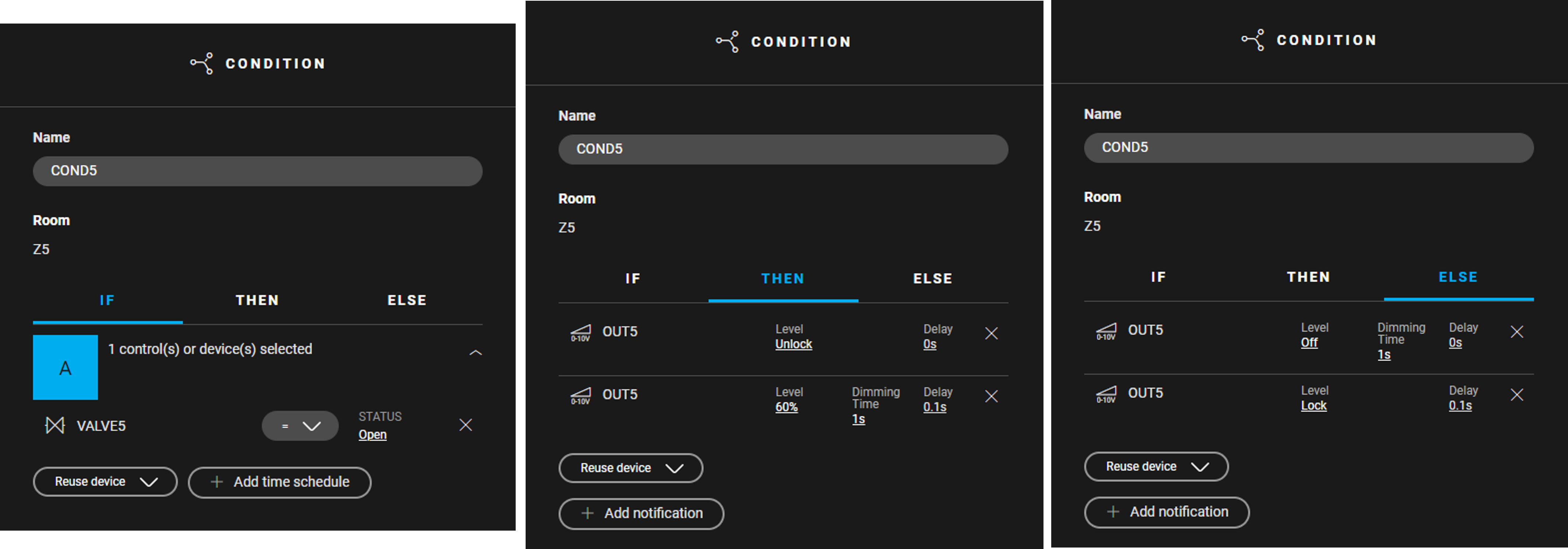
In Z2 to Z6 follow the steps described above but use the data in the table below.
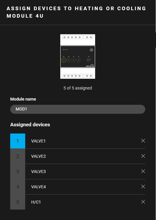
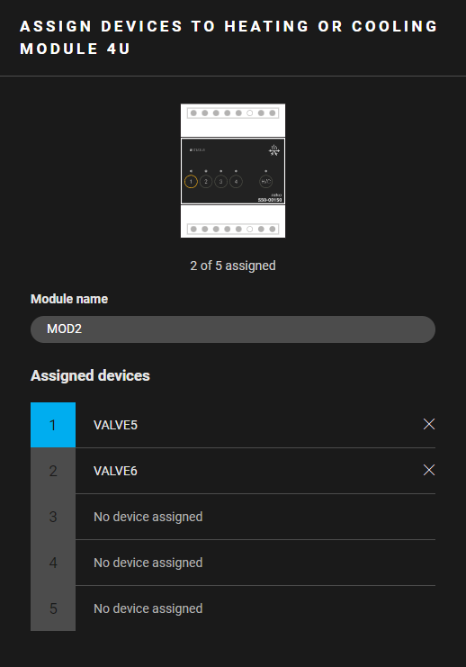
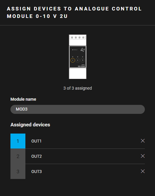
Filling the cabinet and addressing the devices
-
You can assign a maximum of four zone valves on a heating or cooling module 4U.
Contact 5 of that module is a demand contact or an H/C contact.
|
Fill the cabinet with ... |
and address the following devices ... |
|---|---|
|
a heating or cooling module 4U (MOD1) |
|
|
a heating or cooling module 4U (MOD2) |
the zone valves VALVE5 and VALVE6. |
|
an analogue control module 0 - 10 V 2U (MOD3) |
the analog outputs OUT7 to OUT9. |
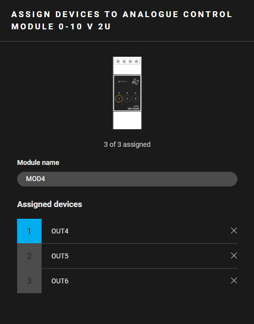
|
an analogue control module 0 - 10 V 2U (MOD4) |
the analog outputs OUT10 to OUT12. |
(*) This contact closes when one of the thermostats demands heating and opens when none of the thermostats demands heating.
Depending on how the heating system is designed, this contact may not need to be connected to the heating system.
Example
Click here to download the programming example.
(FPE_026_222_1.nhc2 file).
Wiring diagram
