Det här steget fungerar bara i Belgien och Nederländerna.
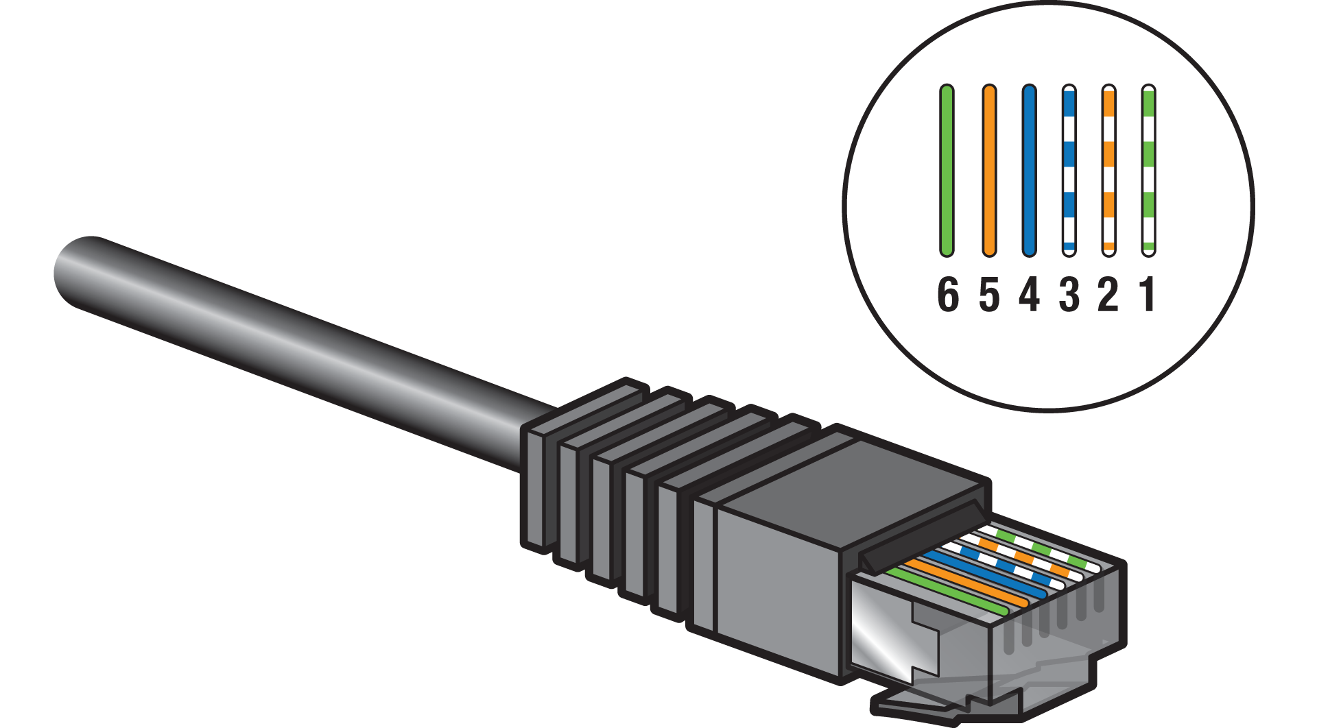
P1-kabelkrav
Beroende på avståndet mellan den trådlösa bryggan och den smarta/digitala mätaren kan du använda en av följande lösningar:
|
Avstånd |
Lösning |
|---|---|
|
< 2 m |
Använd den medföljande P1-kabeln. |
|
2–15 m |
Sätt ihop en längre kabel:
|
|
> 15 m |
Skapa en P1-kabelförlängning, se https://guide.niko.eu/en/connhc2/lv/general-solution-p1-cable-extension-digital-meter |
Undvik att ha elektrisk utrustning med kraftiga ökningar (t.ex. enheter med hög effekt, motoriserade enheter) i närheten av kabeln.
Instruktioner
Steg 1
Anslut din digitala mätares P1-port till den trådlösa bryggan genom att sätta i ena änden av kabeln i P1-porten (inte S1-porten!) och den andra änden i den trådlösa bryggan.

Steg 2

* Rulla ihop överflödig kabel
Steg 3
Kontakta ditt distributionsbolag för att aktivera P1-porten på den smarta/digitala mätaren.
Om din Niko Home Control-installation innehåller en global energimätningskanal kommer den att åsidosättas när den trådlösa bryggan ansluts till den digitala mätaren
Kända begränsningar
-
Om du har en installation med bussledningar som redan är utrustad med elmätare och du har lagt till en trådlös brygga som läser av din smarta/digitala mätares energidata. I Niko Home Controls programvara för programmering ställer du in sensorparametern ”avläsningstyp” på avläsning elektricitet enfas eller avläsning elektricitet trefas till ”undermätare” istället för ”global mätare”. På så sätt undviker du att den smarta/digitala mätarens avläsningar och den vanliga mätarens avläsningar läggs ihop. För att undvika problem med användargränssnittet i energigraferna bör du sätta strömtängerna på olika undermätningskretsar
-
Du kan inte förlänga USB-kabeln