Components
The following articles are required to install a Niko Rocker or Niko Toggle for Niko Home Control:
-
a base for a double or fourfold push button (A)
-
a Toggle or Rocker part or set (B)
-
a faceplate (C)
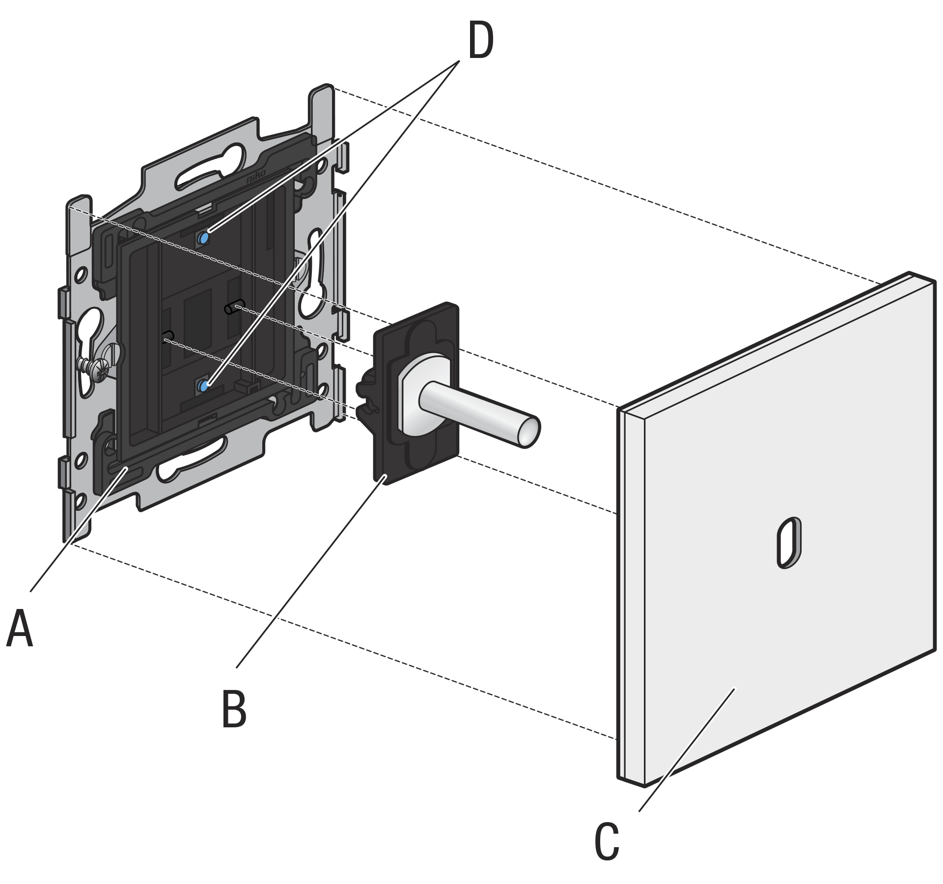
Be aware that each Toggle or Rocker part covers two push-button contacts on the base (D in the image above).
-
You can combine multiple bases, depending on the available faceplates.
-
The base is available with claw and screw fixing.
Installation when using the comfort sensors
Hardware requirements
-
To use the temperature sensor in a thermostat function, your Niko Home Control installation needs to be equipped with the necessary heating or cooling module and connected controller.
-
To use the humidity sensor in a ventilation function, your Niko Home Control installation needs to be equipped with the necessary ventilation module and connected controller.
Placement
-
This product may only be used as a thermostat in normal residential conditions.
-
To enable heating/cooling zone control, make sure the room temperature can be measured precisely by eliminating as many factors as possible that may inhibit the thermostat’s ability to perform accurate temperature control.
-
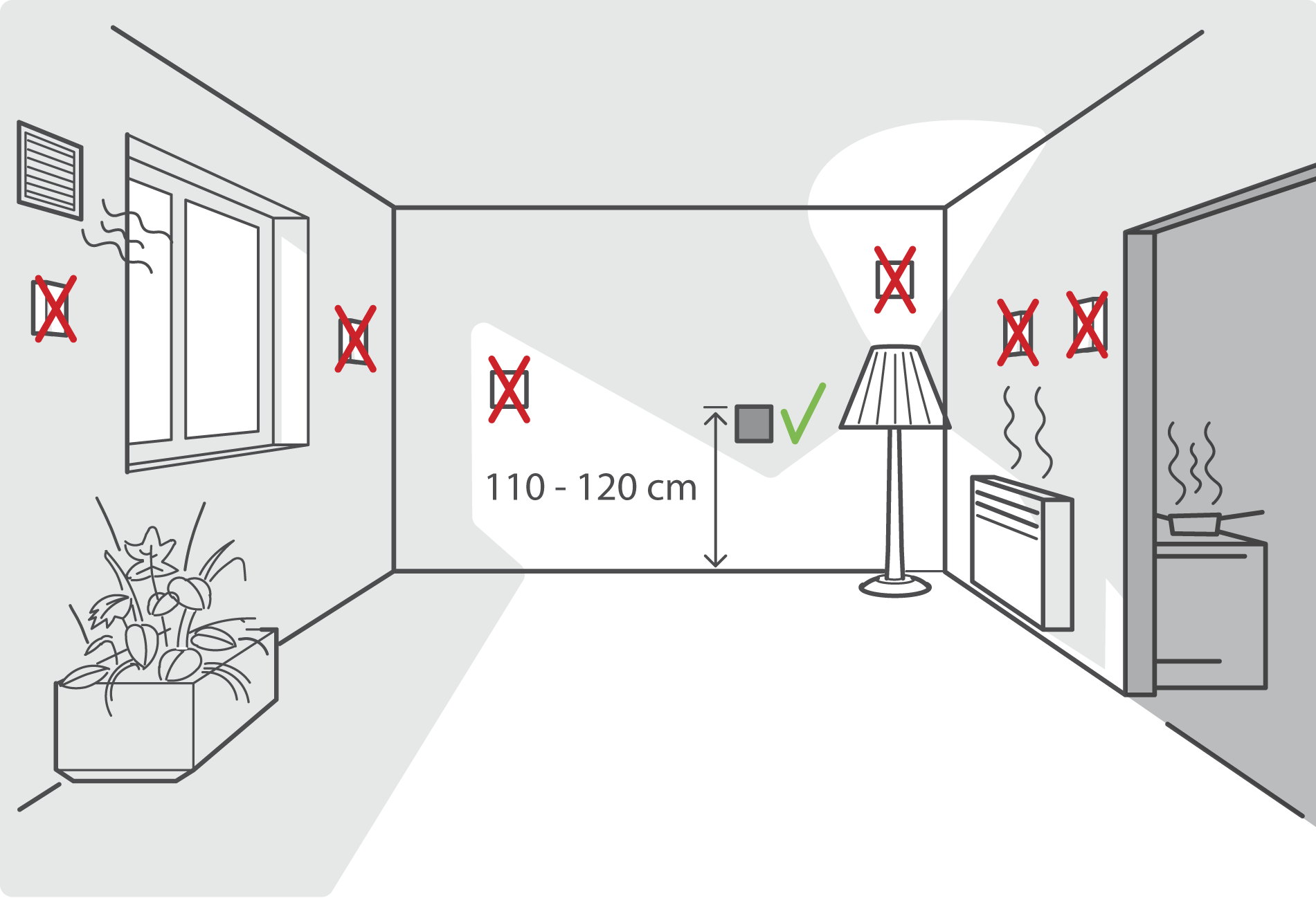
When used as a thermostat, DO NOT mount the push button:
-
in direct sunlight
-
on an exterior wall
-
behind a curtain
-
within the immediate vicinity of a heat-generating source (heater, radiator, etc.) or electrical equipment that may radiate heat (TV, computer, etc.)
-
-
The recommended installation height is 110-120 cm.
-
Do not allow air to circulate behind the control. If needed, use an airtight wall-mounting box or fill in any gaps in the flush-mounting box or bus cable duct using PU foam.
-
Make sure to give the temperature sensor sufficient time to acclimatize, getting to the right operational temperature to measure accurately.
Wiring
230 V – OFF
The terminal pair that is marked with “B” acts as the Niko Home Control bus wiring interface (non-polarized, free topology):
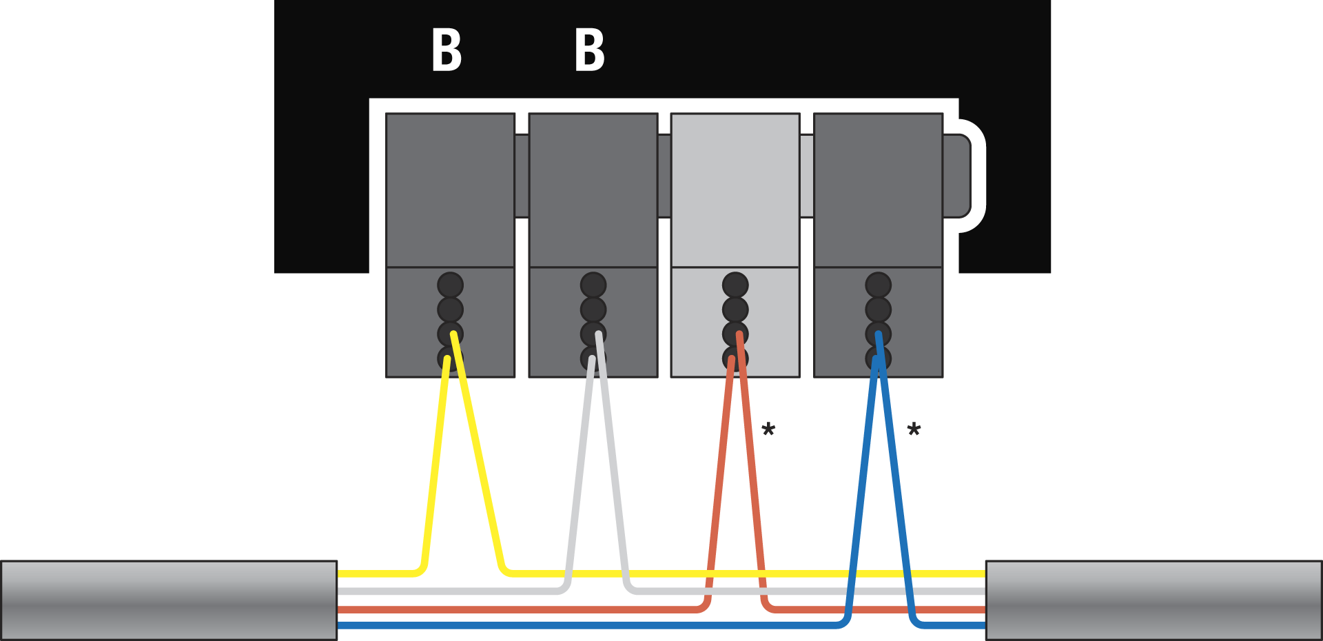
* Not connected to the product, but it is recommended as best practice to use this terminal pair to daisy chain the supplementary wire pair (e.g. to distribute 24 V across the installation for other functions).
Installation instructions
230 V – OFF
Step 1
You can detach the connectors to easily install the wiring:
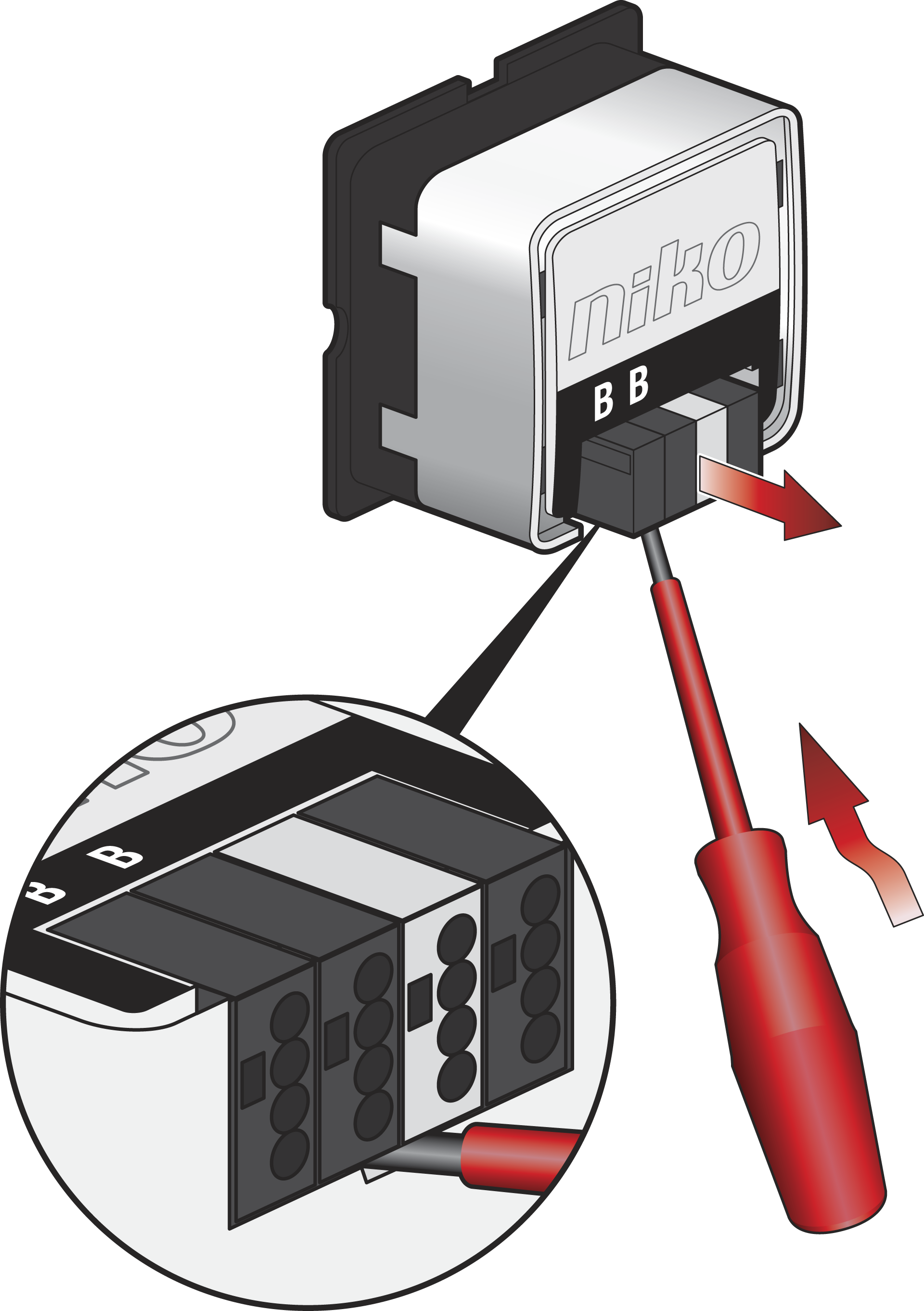
Step 2
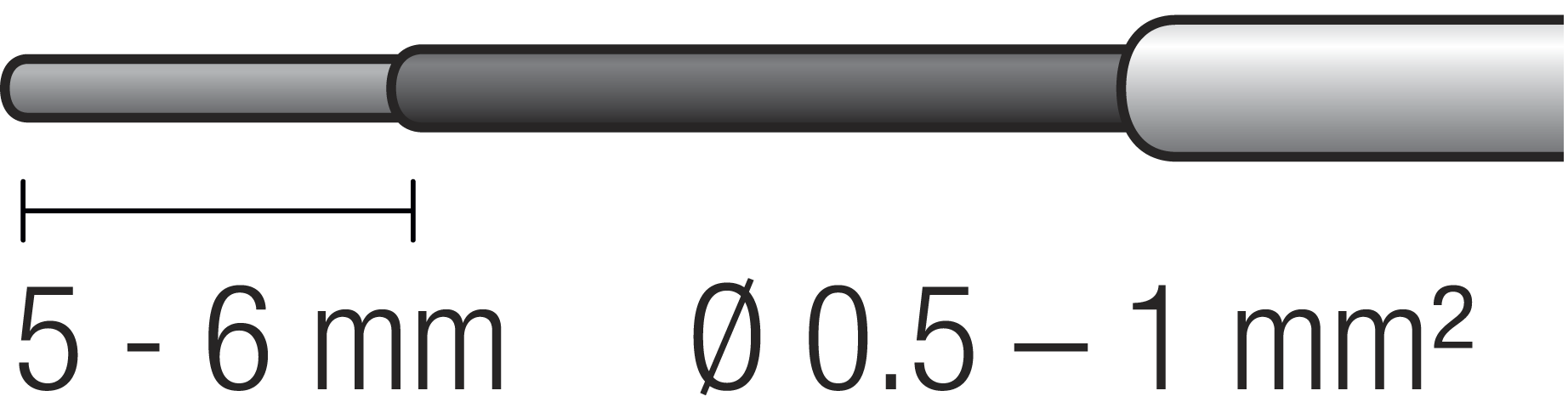
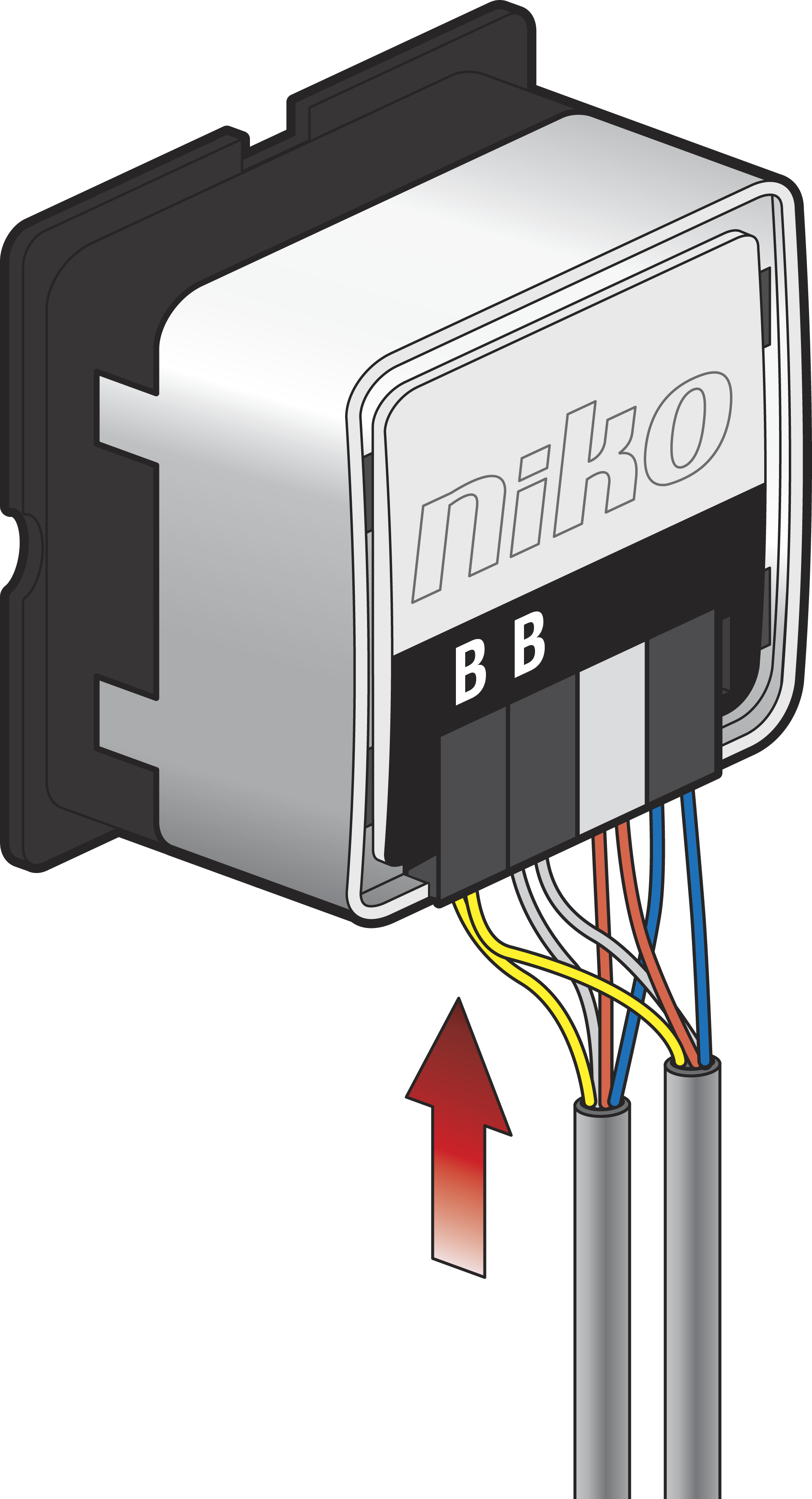
Use wires with the correct diameter and stripping length:
Install the wiring, according to the wiring diagram.
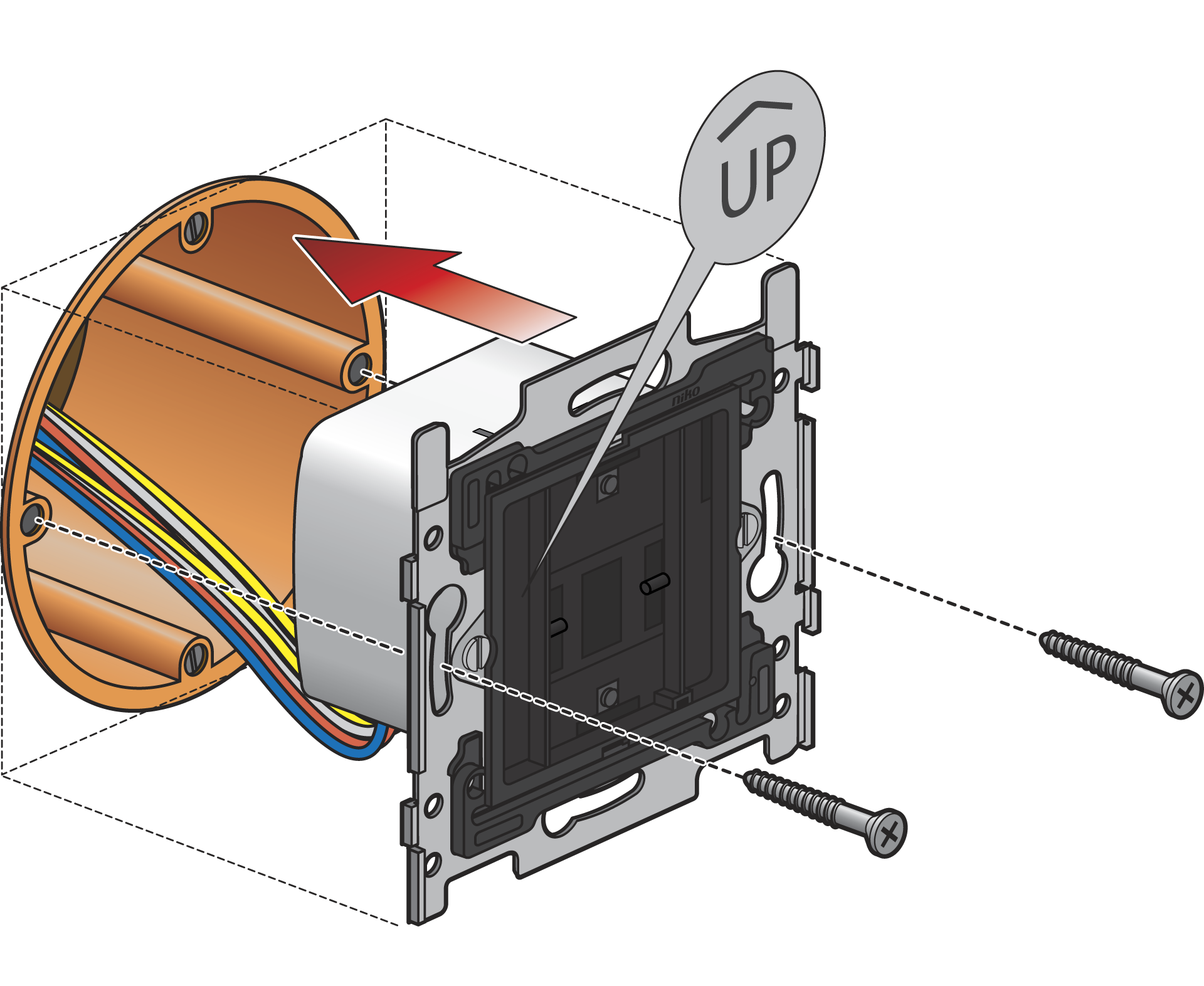
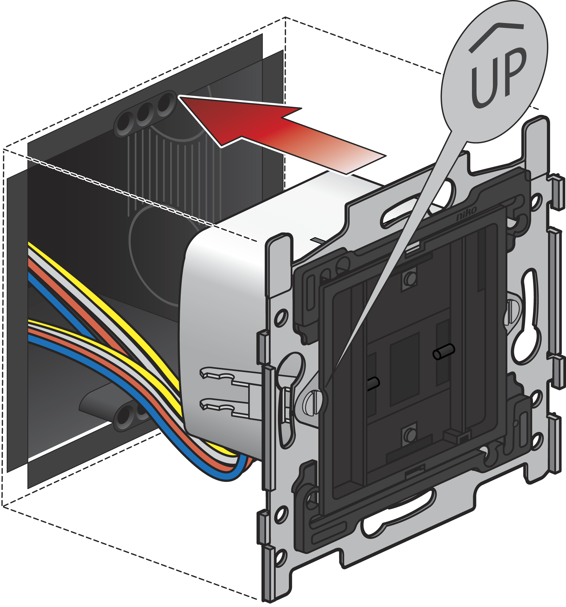
Step 3
The orientation is correct when the “UP” icon is pointing to the upper side.
Mount the base in a flush-mounting box with a depth of at least 40 mm.
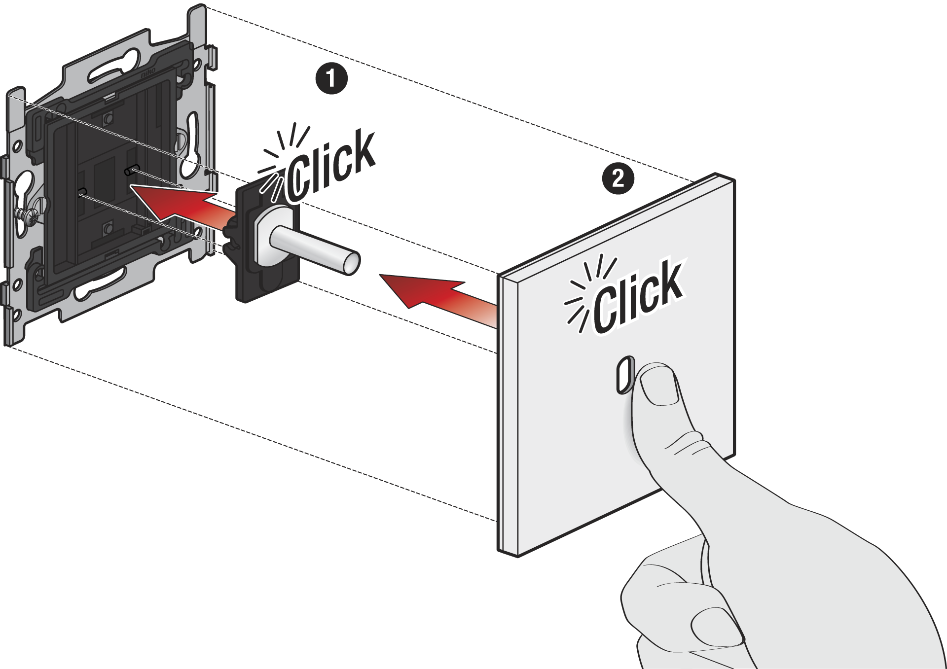
Step 4
Click the Rocker or Toggle part(s) onto the base before you click the faceplate into place.