Was benötigen Sie dazu?
Anforderungen Niko
Ihre Niko Home Control-Installation erfüllt die folgenden Anforderungen:
-
Sie hat einen drahtlosen intelligenten Hub oder einen connected Controller II.
-
Es wurde mit der neuesten Programmiersoftware konfiguriert.
Je nach den Basismodulen Ihrer Niko Home Control-Installation müssen Sie die folgenden zusätzlichen Produkte installieren:
|
|
Erforderliche Zusatzprodukte |
Referenznummern |
|---|---|---|
|
Connected Controller |
Digitales potentialfreies Sensormodul mit einem freien Eingang pro Signal, das Sie in Niko Home Control verwenden möchten Wenn der Ausgangskontakt Ihres Fremdgerätes nicht potentialfrei ist, benötigen Sie ein zusätzliches potentialfreies Kontaktmodul (z. B. Finder 22.32.0.230.1xx0 für 230 V Anschlüsse, Finder 22.32.0.012.1xx0 für 12 V DC Anschlüsse, Finder 22.32.0.024.1xx0 für 24 V DC Anschlüsse) |
|
|
Connected Controller mit drahtloser Bridge |
Vernetzter (Doppel-) Schalter mit einem freien Eingang (E) pro Signal, das Sie in Niko Home Control verwenden möchten Wenn der Ausgangskontakt Ihres Fremdgerätes nicht 230 V hat, benötigen Sie ein zusätzliches 230-V-Kontaktmodul (z. B. Finder 22.32.0.230.1xx0 für potentialfreie Anschlüsse, Finder 22.32.0.012.1xx0 für 12 V DC Anschlüsse, Finder 22.32.0.024.1xx0 für 24 V DC Anschlüsse) Der vernetzte (Doppel-)Schalter kann mit einem modularen Halter (z. B. Legrand 412950) auf einer DIN-Schiene montiert werden. |
|
|
Drahtloser intelligenter Hub |
Vernetzter (Doppel-) Schalter mit einem freien Eingang (E) pro Signal, das Sie in Niko Home Control verwenden möchten Wenn der Ausgangskontakt Ihres Fremdgerätes nicht 230 V hat, benötigen Sie ein zusätzliches 230-V-Kontaktmodul (z. B. Finder 22.32.0.230.1xx0 für potentialfreie Anschlüsse, Finder 22.32.0.012.1xx0 für 12 V DC Anschlüsse, Finder 22.32.0.024.1xx0 für 24 V DC Anschlüsse) Der vernetzte (Doppel-)Schalter kann mit einem modularen Halter (z. B. Legrand 412950) auf einer DIN-Schiene montiert werden. |
Anforderungen an Drittanbieter
Your system meets the following requirements:
-
It has a potential-free or 12/24 V DC or 230 V AC output contact that provides information about the status of the door, gate or window.
-
It is compatible with the Niko module (see Niko requirements).
Verkabelungsdiagramme
Anschließen des Sensormoduls
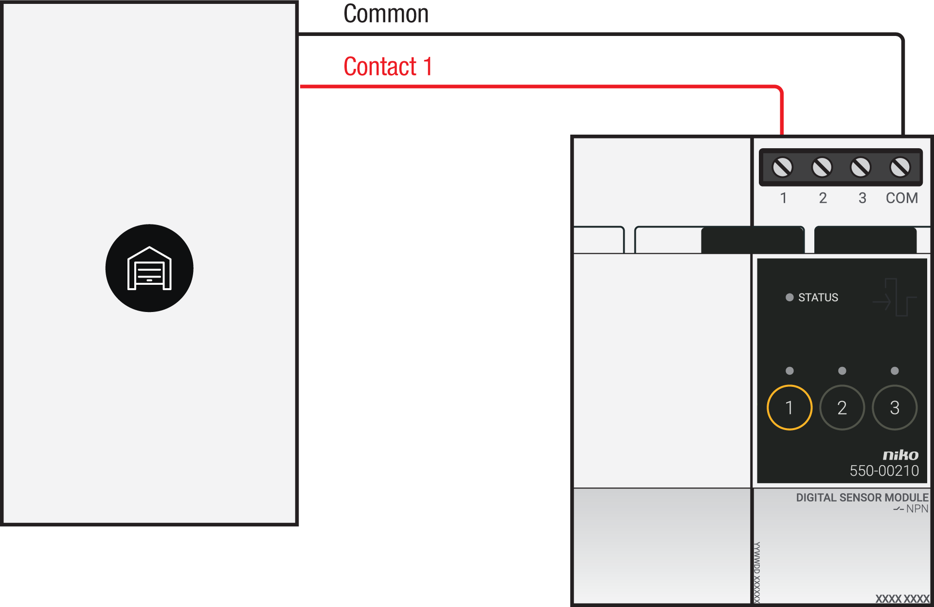
Via potential-free output contact
Connect contact 1 on the Niko sensor module to the output on the third-party system, as shown in the wiring diagram.
Via 230 V or 12/24 V output contact
If your door/window status contacts are not potential-free, you additionally need an appropriate potential-free contact module.
Connect contact 1 on the Niko sensor module to the output on the third-party system, as shown in the wiring diagram.
|
230 V output contact |
12/24 V output contact |
|---|---|
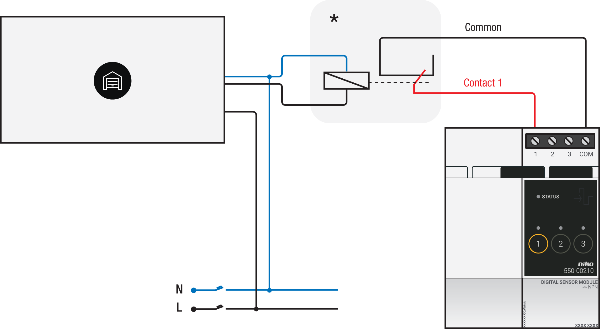
*230 V to potential-free contact module (e.g. Finder 22.32.0.230.1xx0) |
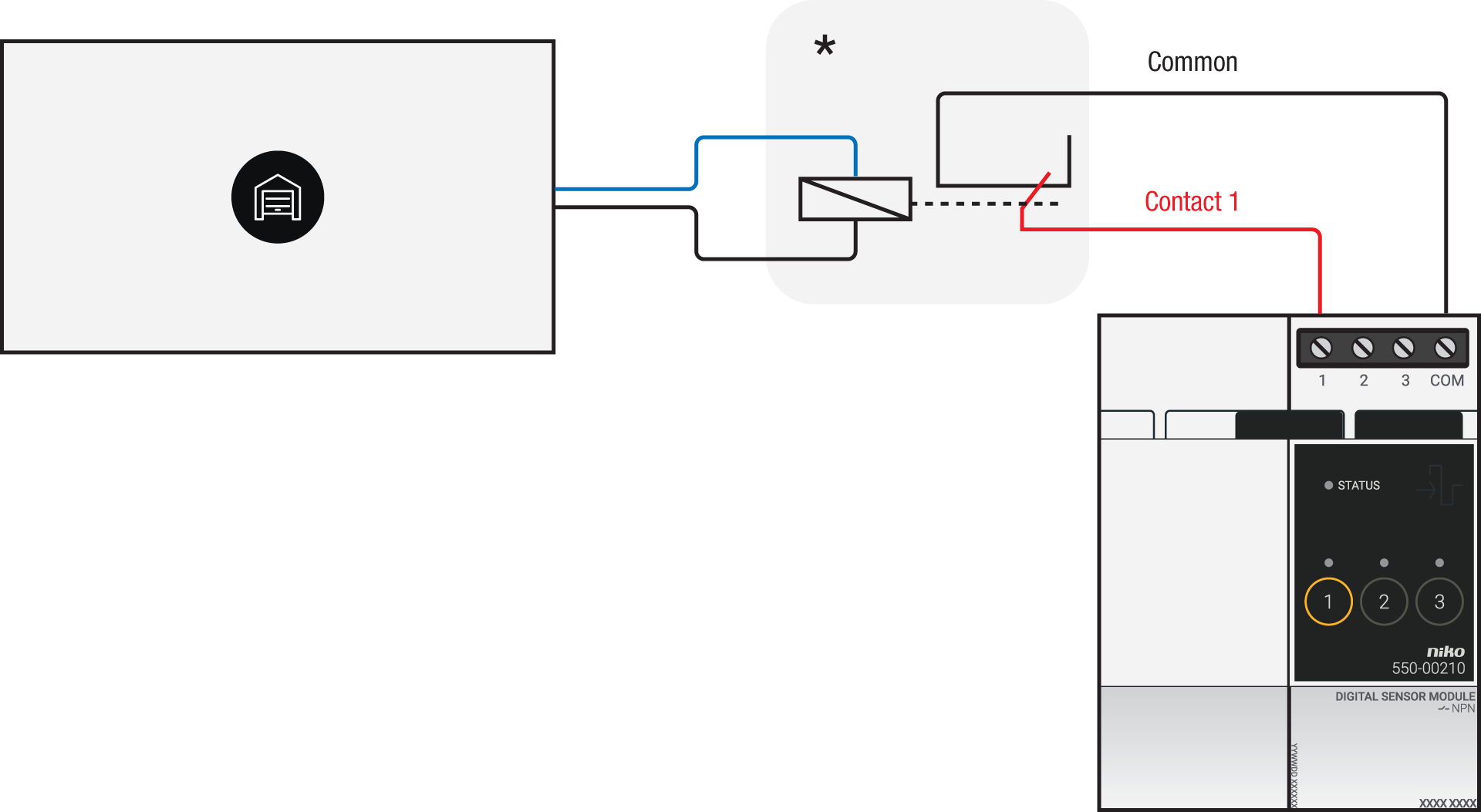
*12 V to potential-free contact module (e.g. Finder 22.32.0.012.1xx0) or 24 V to potential-free contact module (e.g. Finder 22.32.0.024.1xx0) |
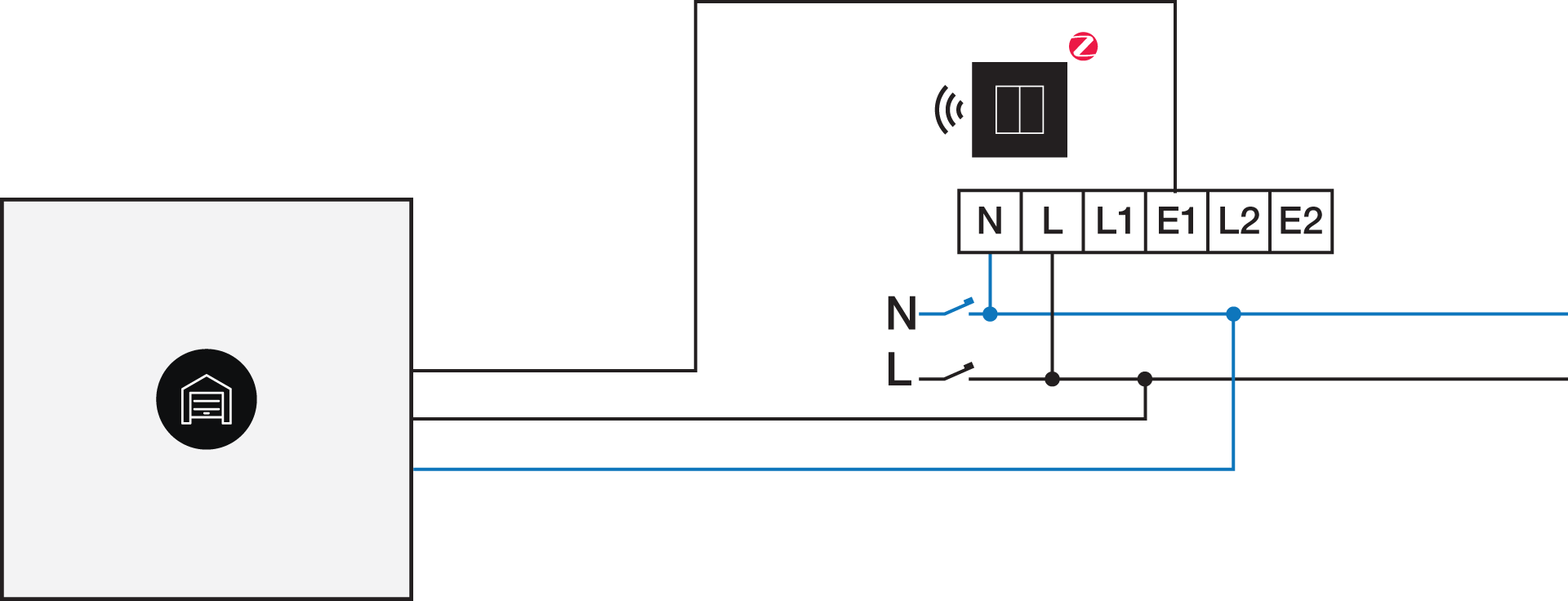
Via potential-free output contact
If your door/window status contacts are not 230 V, you additionally need an appropriate potential-free contact module.
Connect contact 1 on the Niko connected switch to the output on the third-party system, as shown in the wiring diagram.
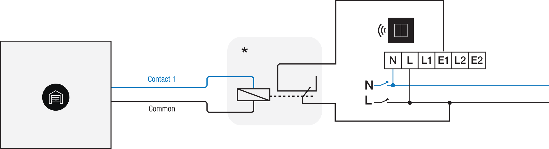
*230 V to potential-free contact module (e.g. Finder 22.32.0.230.1xx0)
Via 230 V or 12/24 V output contact
If your door/window status contacts are not 230 V, you additionally need an appropriate contact module.
Connect contact 1 on the Niko connected switch to the output on the third-party system, as shown in the wiring diagram.
|
230 V output contact |
12/24 V output contact |
|---|---|
|
*12 V to 230 V contact module (e.g. Finder 22.32.0.012.1xx0) or 24 V to 230 V contact module (e.g. Finder 22.32.0.024.1xx0) |
Programmierung
Check if your door or window contact is normally open or normally closed. Adjust the feedback text accordingly.
Configure the potential-free sensor module or connected switch and use its signal to show the status of the door or window via the Niko Home Control programming software.
In case of bus wiring
-
Create a connection to external system.
-
Create a player status:
-
In the behaviour, select the connection to external system.
-
In the parameters, you can enter the text that will be displayed as feedback.
-
In case of traditional wiring
-
Assign the push-button extension to the extension button input (E1) of the connected switch.
-
Set the operating mode of the push-button extension on “push-button mode”.
-
Create a virtual device.
-
Link a basic action between the push-button extension and the virtual device.
-
Create a player status.
-
In the behaviour, select the virtual device.
-
In the parameters, you can enter the text that will be displayed as feedback.
-