Vad behöver du?
Niko-krav
Din Niko Home Control-installation uppfyller följande krav:
-
Den har en trådlös gateway eller en ansluten kontrollenhet II
-
Den är konfigurerad med den senaste programmeringsprogramvaran.
Beroende på vilka grundläggande moduler din Niko Home Control-installation har behöver du installera följande extraprodukter:
|
|
Nödvändiga extraprodukter |
Referensnummer |
|---|---|---|
|
Ansluten kontrollenhet |
Digital potentialfri sensormodul med en ledig ingång per signal som du vill använda i Niko Home Control Om utgångskontakten på din tredjepartsenhet inte är potentialfri behöver du lägga till en potentialfri kontaktmodul (t.ex. Finder 22.32.0.230.1xx0 för 230 V-anslutningar, Finder 22.32.0.012.1xx0 för 12 V DC-anslutningar, Finder 22.32.0.024.1xx0 för 24 V DC-anslutningar) |
|
|
Ansluten kontrollenhet med en trådlös brygga |
Smart (dubbel) strömställare med en ledig ingång (E) per signal som du vill använda i Niko Home Control Om utgångskontakten på din tredjepartsenhet inte är 230 V behöver du lägga till en 230 V-kontaktmodul (t.ex. Finder 22.32.0.230.1xx0 för potentialfria anslutningar, Finder 22.32.0.012.1xx0 för 12 V DC-anslutningar, Finder 22.32.0.024.1xx0 för 24 V DC-anslutningar) Den smarta (dubbla) strömställaren kan placeras på en DIN-skena med en modulär hållare (t.ex. Legrand 412950) |
|
|
Trådlös gateway |
Smart (dubbel) strömställare med en ledig ingång (E) per signal som du vill använda i Niko Home Control Om utgångskontakten på din tredjepartsenhet inte är 230 V behöver du lägga till en 230 V-kontaktmodul (t.ex. Finder 22.32.0.230.1xx0 för potentialfria anslutningar, Finder 22.32.0.012.1xx0 för 12 V DC-anslutningar, Finder 22.32.0.024.1xx0 för 24 V DC-anslutningar) Den smarta (dubbla) strömställaren kan placeras på en DIN-skena med en modulär hållare (t.ex. Legrand 412950) |
Krav från tredje part
Your system meets the following requirements:
-
It has a potential-free or 12/24 V DC or 230 V AC output contact that provides information about the status of the door, gate or window.
-
It is compatible with the Niko module (see Niko requirements).
Kopplingsscheman
Anslut sensormodulen
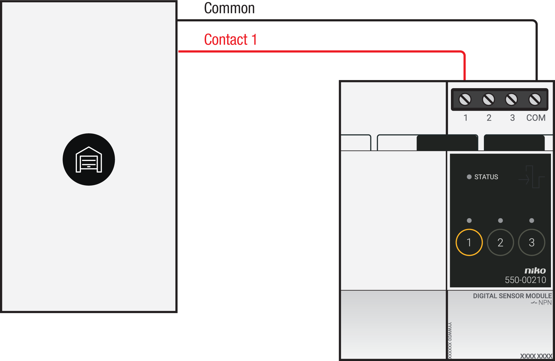
Via potential-free output contact
Connect contact 1 on the Niko sensor module to the output on the third-party system, as shown in the wiring diagram.
Via 230 V or 12/24 V output contact
If your door/window status contacts are not potential-free, you additionally need an appropriate potential-free contact module.
Connect contact 1 on the Niko sensor module to the output on the third-party system, as shown in the wiring diagram.
|
230 V output contact |
12/24 V output contact |
|---|---|
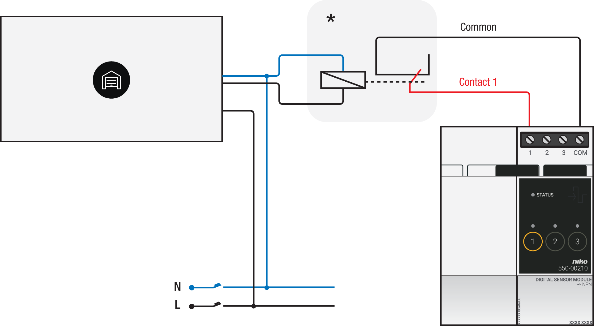
*230 V to potential-free contact module (e.g. Finder 22.32.0.230.1xx0) |
*12 V to potential-free contact module (e.g. Finder 22.32.0.012.1xx0) or 24 V to potential-free contact module (e.g. Finder 22.32.0.024.1xx0) |
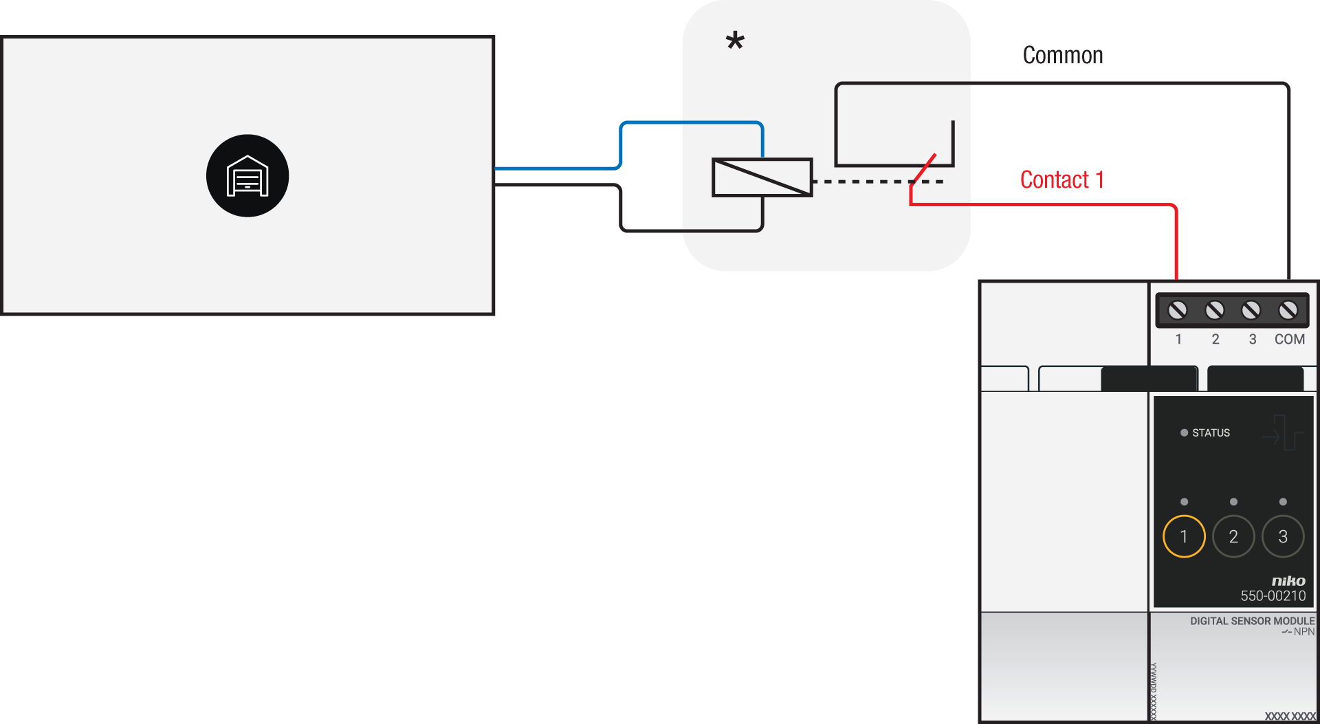
Via potential-free output contact
If your door/window status contacts are not 230 V, you additionally need an appropriate potential-free contact module.
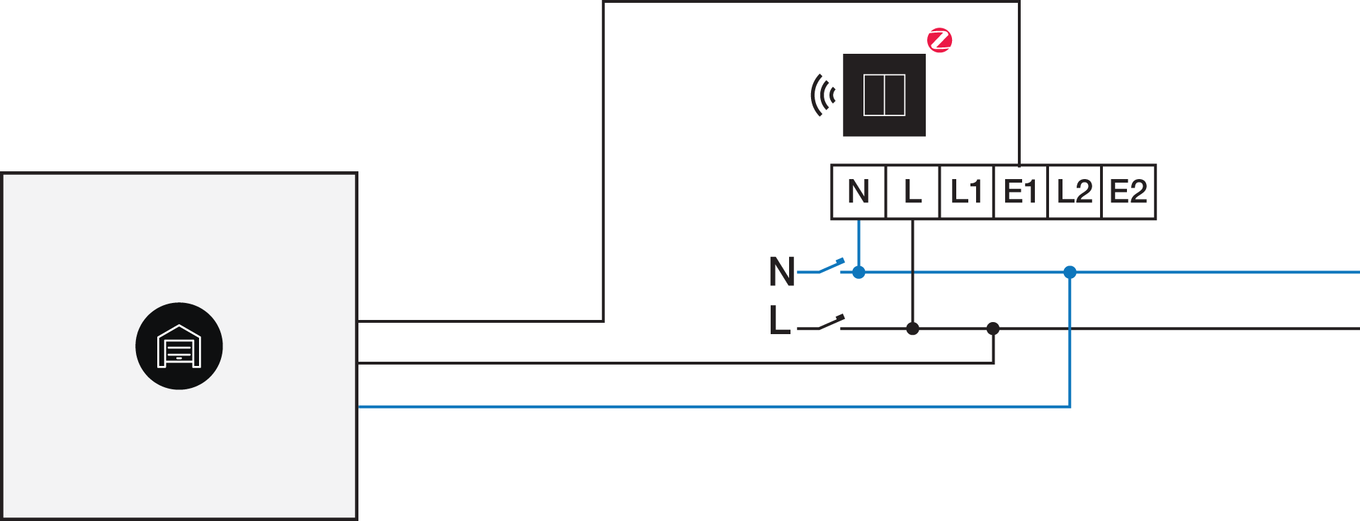
Connect contact 1 on the Niko connected switch to the output on the third-party system, as shown in the wiring diagram.
*230 V to potential-free contact module (e.g. Finder 22.32.0.230.1xx0)
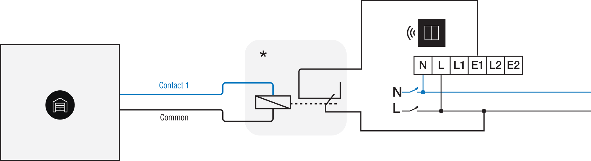
Via 230 V or 12/24 V output contact
If your door/window status contacts are not 230 V, you additionally need an appropriate contact module.
Connect contact 1 on the Niko connected switch to the output on the third-party system, as shown in the wiring diagram.
|
230 V output contact |
12/24 V output contact |
|---|---|
|
*12 V to 230 V contact module (e.g. Finder 22.32.0.012.1xx0) or 24 V to 230 V contact module (e.g. Finder 22.32.0.024.1xx0) |
Programmering
Check if your door or window contact is normally open or normally closed. Adjust the feedback text accordingly.
Configure the potential-free sensor module or connected switch and use its signal to show the status of the door or window via the Niko Home Control programming software.
In case of bus wiring
-
Create a connection to external system.
-
Create a player status:
-
In the behaviour, select the connection to external system.
-
In the parameters, you can enter the text that will be displayed as feedback.
-
In case of traditional wiring
-
Assign the push-button extension to the extension button input (E1) of the connected switch.
-
Set the operating mode of the push-button extension on “push-button mode”.
-
Create a virtual device.
-
Link a basic action between the push-button extension and the virtual device.
-
Create a player status.
-
In the behaviour, select the virtual device.
-
In the parameters, you can enter the text that will be displayed as feedback.
-