Čo budete potrebovať?
Požiadavky spoločnosti Niko
Vaša inštalácia Niko Home Control musí spĺňať nasledujúce požiadavky:
-
Musí obsahovať bezdrôtový smart hub alebo connected controller II.
-
Musí byť nakonfigurovaná pomocou najnovšej verzie programovacieho softvéru.
V závislosti od základných modulov vašej inštalácie Niko Home Control je potrebné nainštalovať nasledujúce dodatočné produkty:
|
|
Požadované dodatočné produkty |
Katalógové čísla |
|---|---|---|
|
Connected controller |
Modul digitálneho bezpotenciálového vstupného modulu s jedným voľným vstupom pre každý signál, ktorý chcete používať v systéme Niko Home Control Ak výstupný kontakt na vašom zariadení tretej strany nie je bezpotenciálový, potrebujete dodatočný modul bezpotenciálového kontaktu (napr. Finder 22.32.0.230.1xx0 pre 230 V pripojenie, Finder 22.32.0.012.1xx0 pre 12 V DC pripojenia, Finder 22.32.0.024.1xx0 pre 24 V DC pripojenia). |
|
|
Connected controller s wireless bridge |
(Dvojitý) smart spínač s jedným voľným vstupom (E) pre každý signál, ktorý chcete používať v systéme Niko Home Control Ak výstupný kontakt na vašom zariadení tretej strany nie je 230 V, potrebujete dodatočný modul 230 V kontaktu (napr. Finder 22.32.0.230.1xx0 pre bezpotenciálové pripojenia, Finder 22.32.0.012.1xx0 pre 12 V DC pripojenia, Finder 22.32.0.024.1xx0 pre 24 V DC pripojenia) (Dvojitý) smart spínač je možné umiestniť na DIN lištu pomocou modulárneho držiaka (napr. Legrand 412950) |
|
|
Bezdrôtový smart hub |
(Dvojitý) smart spínač s jedným voľným vstupom (E) pre každý signál, ktorý chcete používať v systéme Niko Home Control Ak výstupný kontakt na vašom zariadení tretej strany nie je 230 V, potrebujete dodatočný modul 230 V kontaktu (napr. Finder 22.32.0.230.1xx0 pre bezpotenciálové pripojenia, Finder 22.32.0.012.1xx0 pre 12 V DC pripojenia, Finder 22.32.0.024.1xx0 pre 24 V DC pripojenia) (Dvojitý) smart spínač je možné umiestniť na DIN lištu pomocou modulárneho držiaka (napr. Legrand 412950) |
Požiadavky tretej strany
Your system meets the following requirements:
-
It has a potential-free or 12/24 V DC or 230 V AC output contact that provides information about the status of the door, gate or window.
-
It is compatible with the Niko module (see Niko requirements).
Schémy zapojenia
Pripojenie vstupného modulu
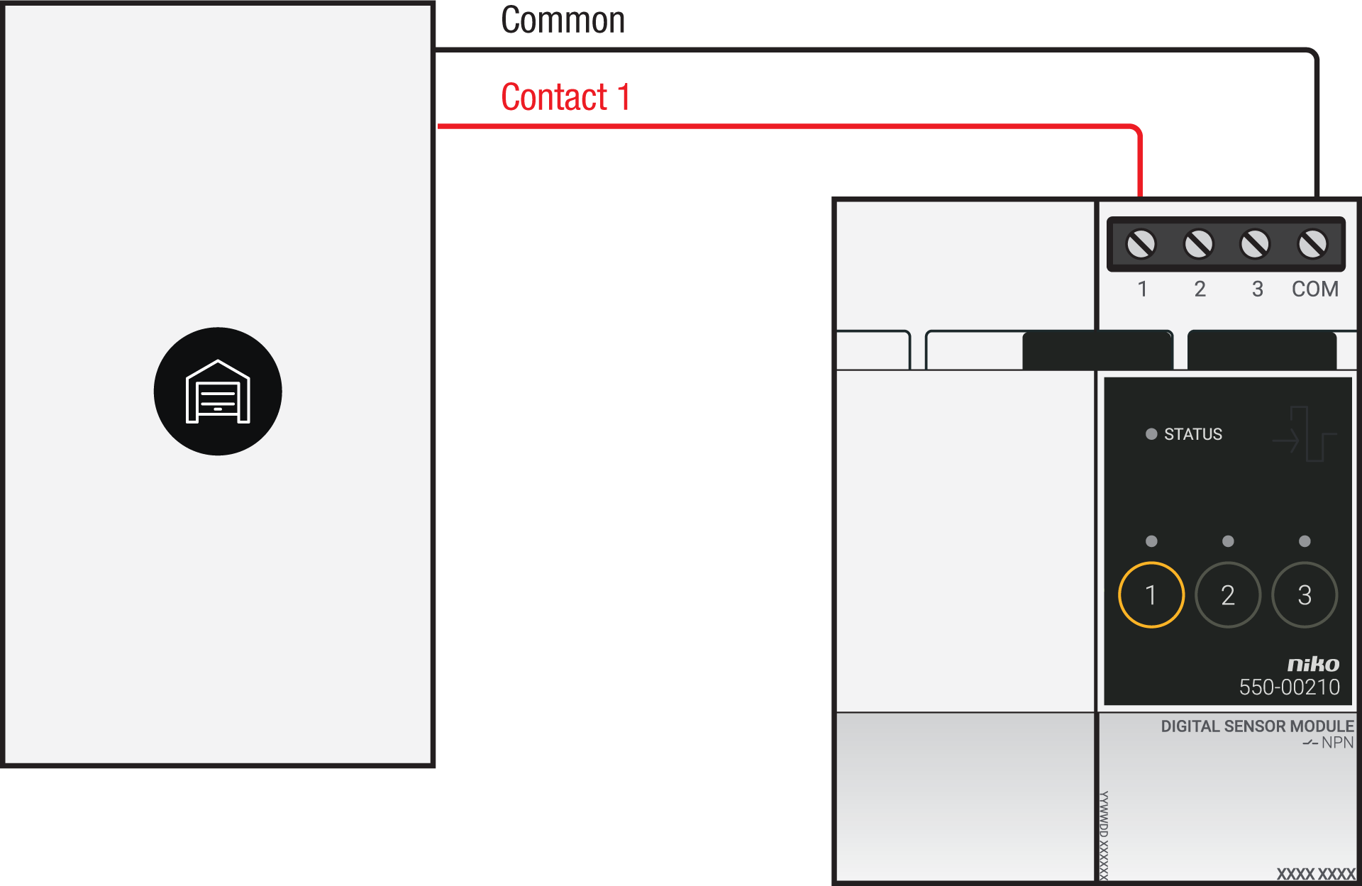
Via potential-free output contact
Connect contact 1 on the Niko sensor module to the output on the third-party system, as shown in the wiring diagram.
Via 230 V or 12/24 V output contact
If your door/window status contacts are not potential-free, you additionally need an appropriate potential-free contact module.
Connect contact 1 on the Niko sensor module to the output on the third-party system, as shown in the wiring diagram.
|
230 V output contact |
12/24 V output contact |
|---|---|
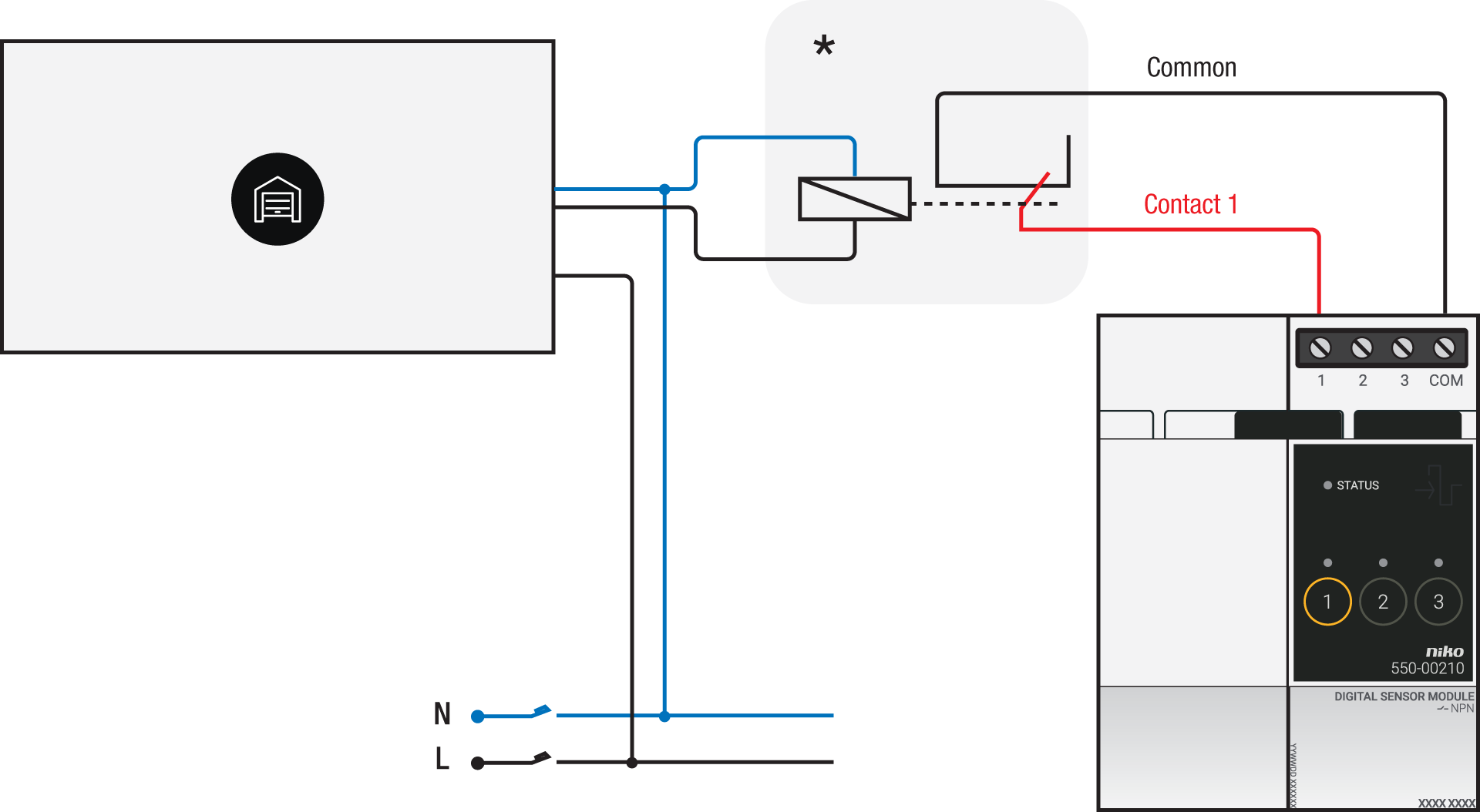
*230 V to potential-free contact module (e.g. Finder 22.32.0.230.1xx0) |
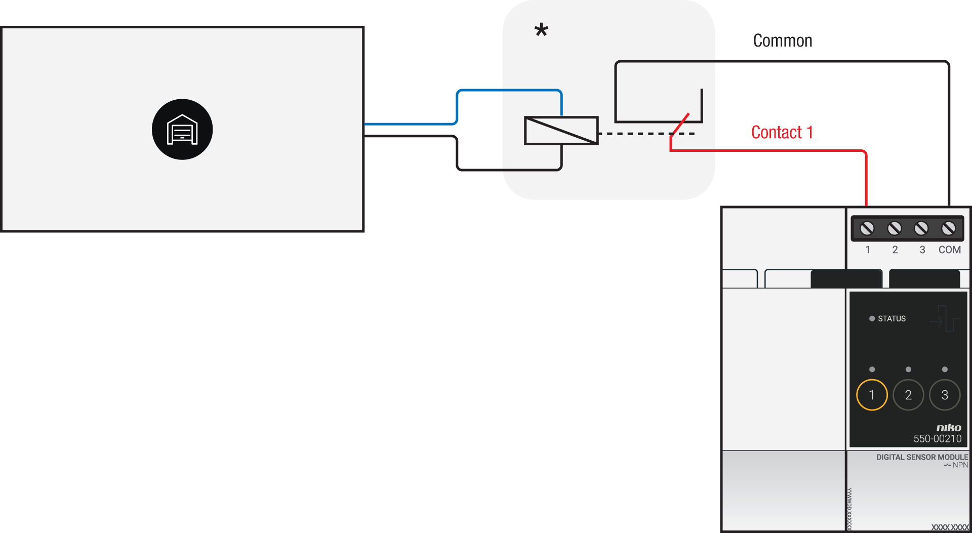
*12 V to potential-free contact module (e.g. Finder 22.32.0.012.1xx0) or 24 V to potential-free contact module (e.g. Finder 22.32.0.024.1xx0) |
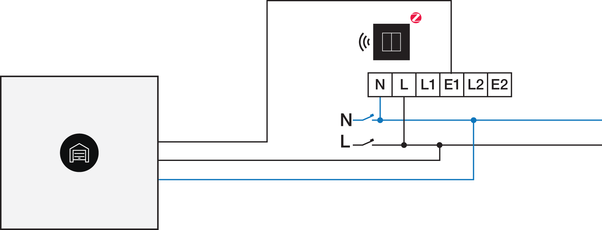
Via potential-free output contact
If your door/window status contacts are not 230 V, you additionally need an appropriate potential-free contact module.
Connect contact 1 on the Niko connected switch to the output on the third-party system, as shown in the wiring diagram.
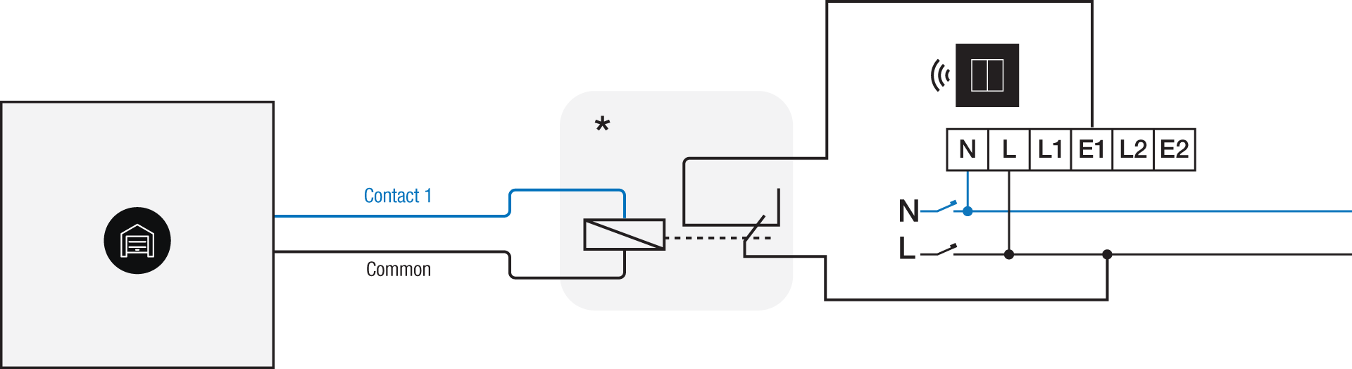
*230 V to potential-free contact module (e.g. Finder 22.32.0.230.1xx0)
Via 230 V or 12/24 V output contact
If your door/window status contacts are not 230 V, you additionally need an appropriate contact module.
Connect contact 1 on the Niko connected switch to the output on the third-party system, as shown in the wiring diagram.
|
230 V output contact |
12/24 V output contact |
|---|---|
|
*12 V to 230 V contact module (e.g. Finder 22.32.0.012.1xx0) or 24 V to 230 V contact module (e.g. Finder 22.32.0.024.1xx0) |
Programovanie
Check if your door or window contact is normally open or normally closed. Adjust the feedback text accordingly.
Configure the potential-free sensor module or connected switch and use its signal to show the status of the door or window via the Niko Home Control programming software.
In case of bus wiring
-
Create a connection to external system.
-
Create a player status:
-
In the behaviour, select the connection to external system.
-
In the parameters, you can enter the text that will be displayed as feedback.
-
In case of traditional wiring
-
Assign the push-button extension to the extension button input (E1) of the connected switch.
-
Set the operating mode of the push-button extension on “push-button mode”.
-
Create a virtual device.
-
Link a basic action between the push-button extension and the virtual device.
-
Create a player status.
-
In the behaviour, select the virtual device.
-
In the parameters, you can enter the text that will be displayed as feedback.
-