Description
Three dimmers and/or switching devices are connected to the Niko Home Control installation using the analogue control module 1-10 V:
-
dimmers with an analogue input of 1-10 V for dimming monochrome LEDs.
-
electronic control gear for fluorescent lights.
-
high-power dimmers with an analogue input of 1-10 V.
Useful Niko reference codes: 05-715, 65-410, 65-412, 65-416, 330-00701.
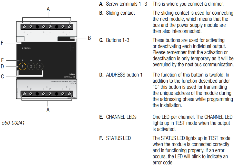
Overview
Operation
The output will send a signal between 1 and 10 V to control the connected dimmer/electronic control gear, which allows programmed actions or mood settings to be activated.
By pressing the corresponding button, the status of each output can be changed manually and temporarily to connect a light. Please remember that the activation or deactivation is only temporary as it will be overruled by the next bus communication.
Installation
Wiring diagram

Follow the steps below to install the module:
-
Ensure that the installation is disconnected from the mains.
-
The distance between the dimmers and the module should not exceed 50m.
-
A maximum of three dimmers can be connected per module.
1 Press the module onto the DIN rail until it clicks into place. Preferably position the module in the top row inside the electrical cabinet to keep the SELV cables separate from the 230V cables.
2 Connect the dimmers to one of the screw terminals 1-3.
It is possible to connect three individual phases.
3 Connect the analogue control module 1-10 V to the module before it. Slide the sliding contact of this module to the right until it clicks into the analogue control module 1-10 V. This will ensure that the bus and the power supply voltage are connected.
Error codes
When the module is functioning properly, the STATUS LED will light up in TEST mode only. If one or several errors occur, the LED will blink to indicate the error code of the error with the highest priority. The table below provides an overview of all error codes.
|
LED |
ACTION |
ERROR |
POSSIBLE SOLUTIONS |
|
STATUS LED |
Blinks – one pulse per two seconds. |
Software error |
Wrong software version. * *Download the latest software version from the Niko website to upgrade the module. |
Technical data
-
3 outputs: 1-10 V (FELV, functional extra-low voltage), current-controlled (I)
-
option of connecting 3 individual phases
-
maximum distance between dimmers and module: 50 m
-
maximum load: 20 mA per channel, protected from 50 mA per channel and maximum 11 V
-
galvanic isolation when connecting the power circuit (6 A per channel)
-
2 x 6 screw terminals for 3 x 1.5 mm² or 2 x 2.5 mm² or 1 x 4 mm²
-
dimensions: DIN 4U
-
sliding contact to connect the module to the following module on the DIN rail
-
ambient temperature: 0 - 45 °C
-
CE marked