Description
The Nikobus interface allows you to expand the existing Nikobus installation by adding several functions of the Niko Home Control installation. Note that programming via PC must be enabled within the Nikobus installation, i.e. at least PC Link, PC Logic or a feedback module is required.
Overview
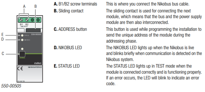
Operation
The Nikobus interface allows you to operate Niko Home Control functions using Nikobus control elements, and vice versa. Functions of the Nikobus installation can only be operated via the generic push buttons of the Niko Home Control installation. Specific push buttons such as push buttons for dimming, motor and ventilation control, or push buttons with display, cannot be used.
-
Feedback is not possible between the acting elements of the Nikobus installation and those of the Niko Home Control installation.
-
Specific Niko Home Control push buttons or push buttons with display cannot be used to operate the functions of a Nikobus installation.
-
A maximum of 100 Nikobus controls can be used per installation. In other words, a maximum of 100 Niko Home Control action buttons can be assigned to one Nikobus installation.
-
A maximum of 100 virtual Nikobus push buttons can be used per installation. In other words, a maximum of 100 Nikobus buttons can be assigned to one Niko Home Control installation.
-
If you need to reprogram the Niko Home Control installation, you do not need to reprogram the Nikobus installation provided that the Nikobus addresses of the Nikobus control and of the virtual Nikobus push buttons have not been modified.
Operating a Nikobus module using a Niko Home Control action button
1 Link the Nikobus control to an action in the Niko Home Control installation.
This Nikobus control behaves like an output, but instead of controlling a contact, the Nikobus interface sends an address to the Nikobus installation.
Use one Nikobus control for each Niko Home Control action. If you use a push button with six action buttons, you will need to provide six Nikobus controls.
The address you need to select or enter in the Nikobus software can be found under the parameters of the Nikobus control for this action button.
2 Use the Nikobus software to manually add one virtual Nikobus push button per Nikobus control. The virtual push button can be connected to any Nikobus module with single or dual-button mode:
-
Select dual-button mode if you want to activate and deactivate the action via the Niko Home Control action button.
-
Select single-button mode if the action is only to be started via the Niko Home Control action button.
3 Go to the “Address/Parameters”tab sheet in the Nikobus software to add the address you selected or received while programming the Niko Home Control installation to this virtual push button.
Operating a Niko Home Control module using a Nikobus push button
1 Find the address of the Nikobus push button that you wish to use.
2 While programming the Niko Home Control installation, add a virtual Nikobus push button for the action you wish to execute.
Link the Nikobus push buttons to the virtual Nikobus push button. The same method as with all other Niko Home Control push buttons is used to assign and address this virtual push button.
Enter the following parameters for the virtual Nikobus push button:
-
the address of the Nikobus push button.
-
the actual button on the Nikobus push button that you want to use for activating the action: A, B, C or D
Installation
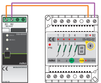
Wiring diagram
-
Ensure that the installation is disconnected from the power mains when setting up the electrical cabinet.
-
The bus cables of the Nikobus installation are not compatible with those of the Niko Home Control installation. Connecting cables from both systems to one another may cause damage.
Follow the steps below to install the Nikobus interface:
1 Press the Nikobus interface onto the DIN rail until it clicks into place. Preferably position the interface in the top row inside the electrical cabinet to keep the cables separate from the 230V cables.
2 Connect the Nikobus cables to screw terminals B1 and B2.
Error codes
When the module is functioning properly, the NIKOBUS LED will light up in rest mode and the STATUS LED of the module will light up in TEST mode only. If one or several errors occur, the STATUS LED will blink to indicate the error code of the error with the highest priority. The table below provides an overview of all error codes.
|
LED |
ACTION |
ERROR |
POSSIBLE SOLUTIONS |
|
STATUS LED |
Blinks – one pulse per two seconds. |
Software error |
Wrong software version.* *Download the latest software version from the Niko website to upgrade the module. |
|
Blinks – two pulses per two seconds. |
No Nikobus voltage detected. |
Check the cables. Check whether the Nikobus installation is functioning properly. Add a Nikobus module to supply bus power. |
|
|
NIKOBUS LED |
Does not light up: |
Technical data
-
dimensions: DIN 2E
-
sliding contact to connect the module to the following module on the DIN rail
-
2 screw terminals for 3 x 1.5 mm² or 2 x 2.5 mm² or 1 x 4 mm²
-
CE marked
-
in conformity with EN 60669-2-1
-
ambient temperature: 0 - 45 °C
-
short-circuit and overheating protections