The installation should be carried out by a qualified installer and in accordance with the regulations of the local distribution system operator.
Step 1
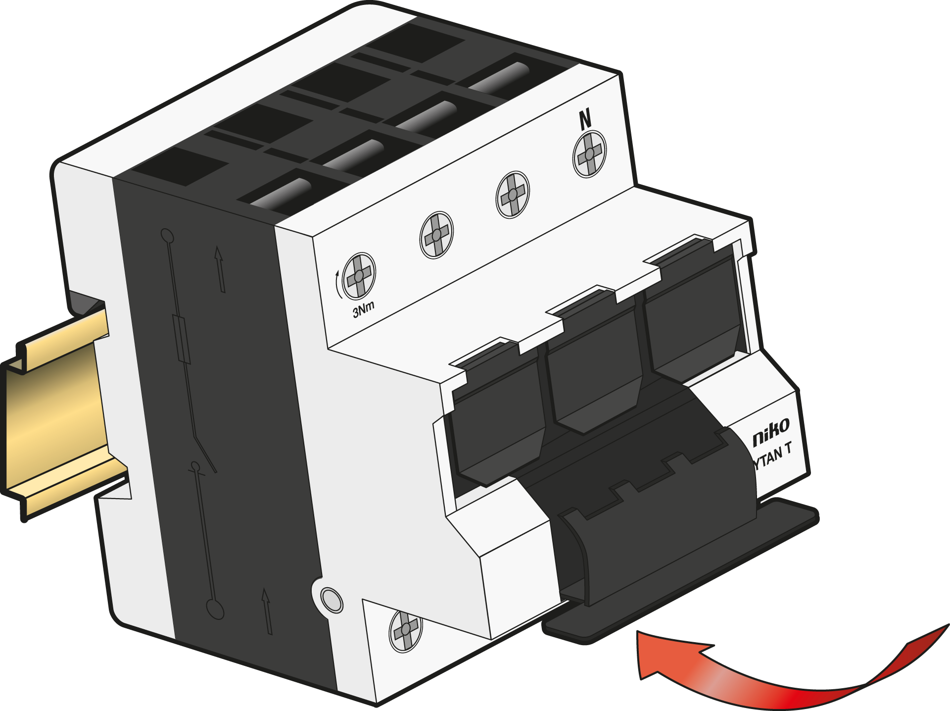
Click onto the DIN rail.
Pay attention to the rated diversity factor (RDF) according to IEC/EN 61439-1.
Step 2
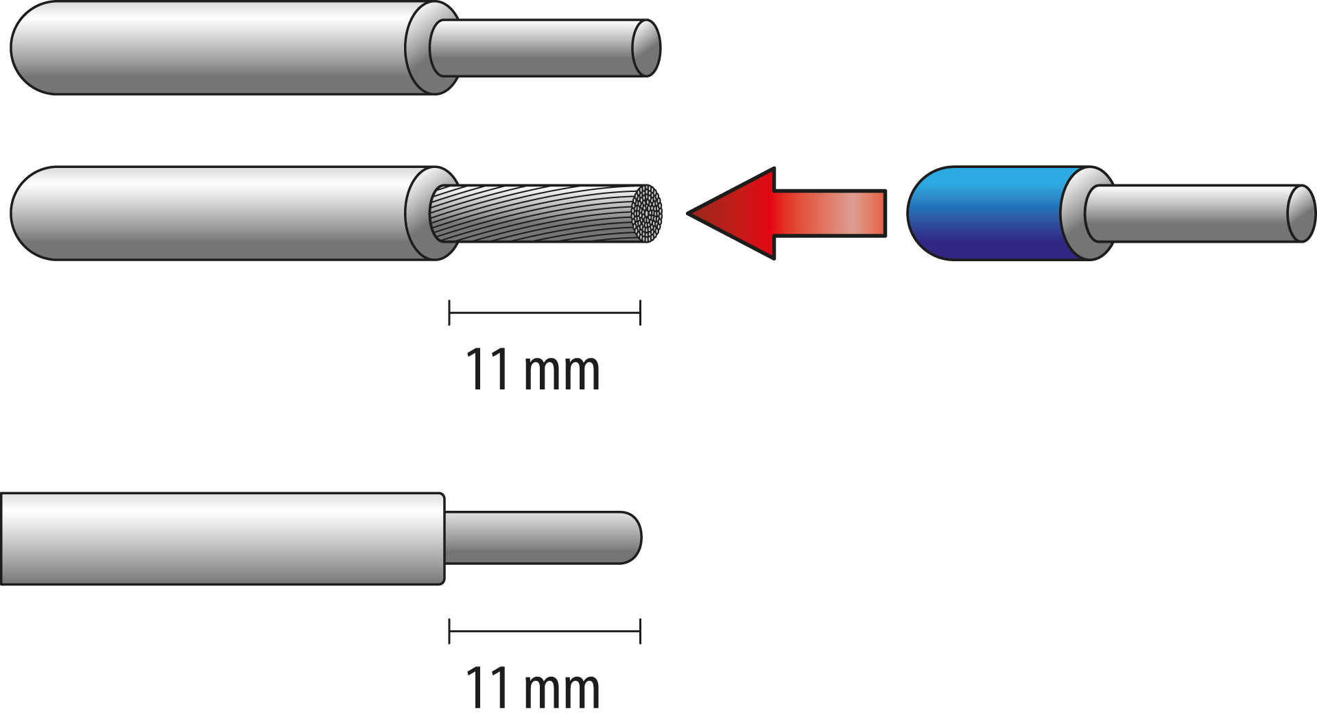
Only use suitable wires:
-
Copper
-
Rigid, stranded or flexible
-
Cross section 1,5 – 35 mm2
Strip the wires. Use ferrules for flexible wires.
Step 3
Optionally, connect the main protection relay and up to 12 fuse switch disconnectors, using TYTAN® HC bus cables (961-9620300).
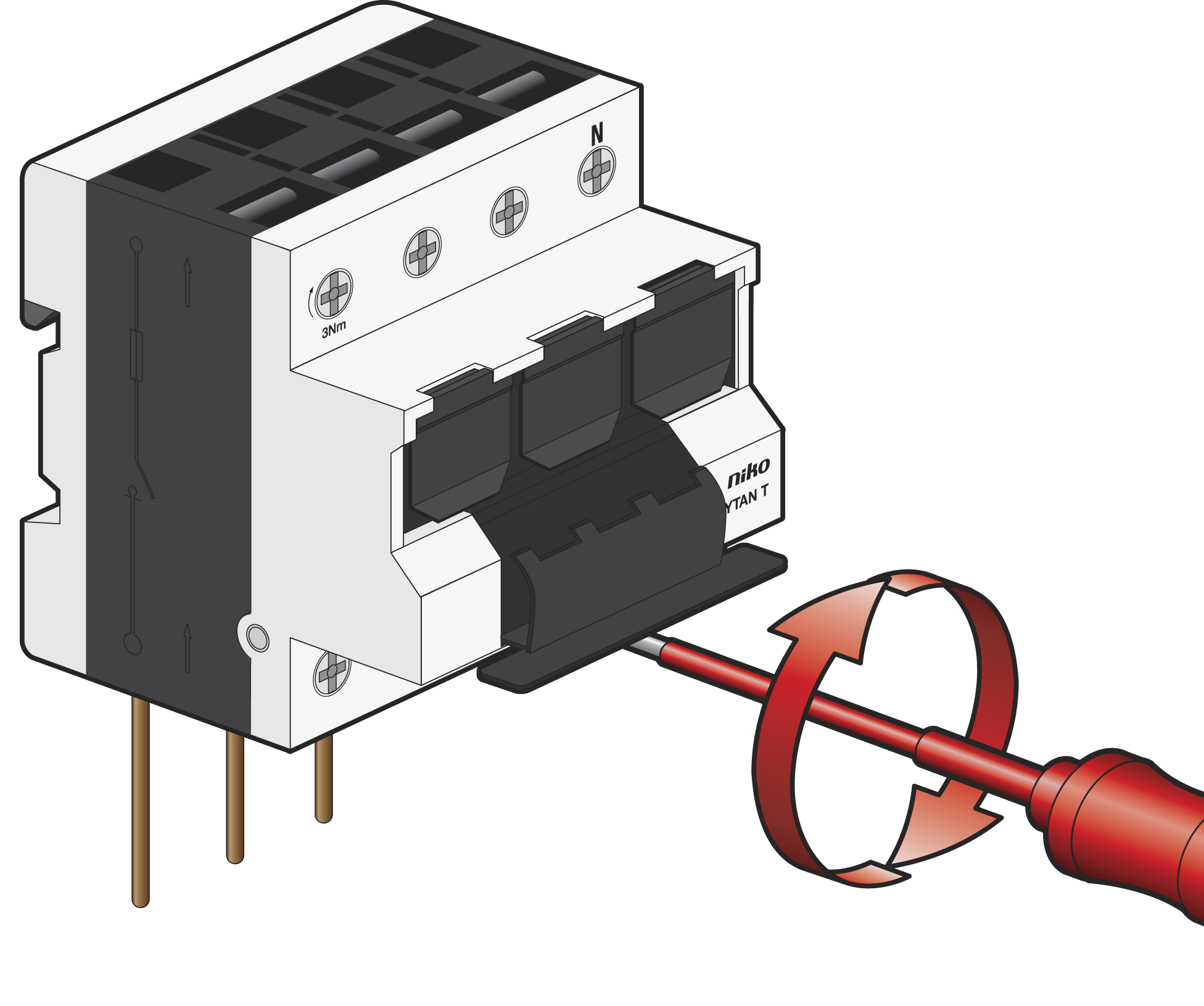
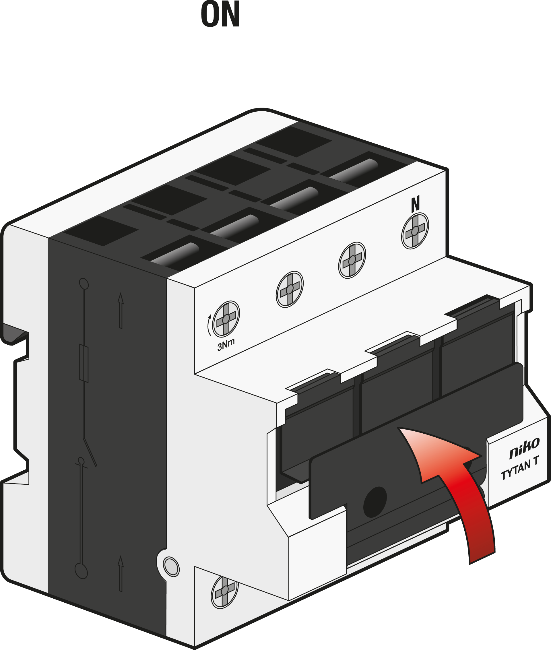
Feed the main wires at thebottom of the fuse switch disconnector, and the consumption at the top. Secure with 3 Nm, using a PZ2 screw driver.
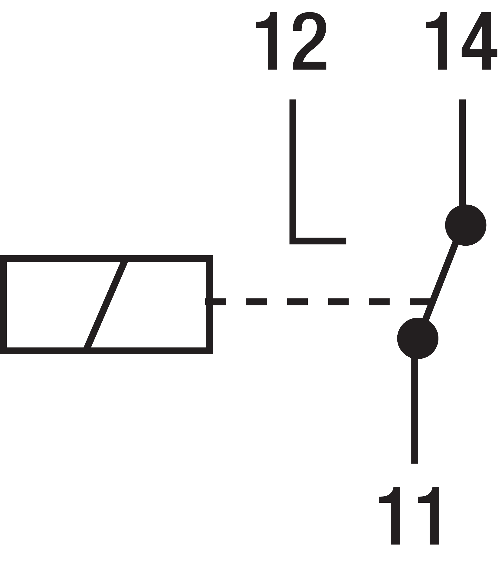
Use the wiring diagram to connect the wires correctly.
Step 4
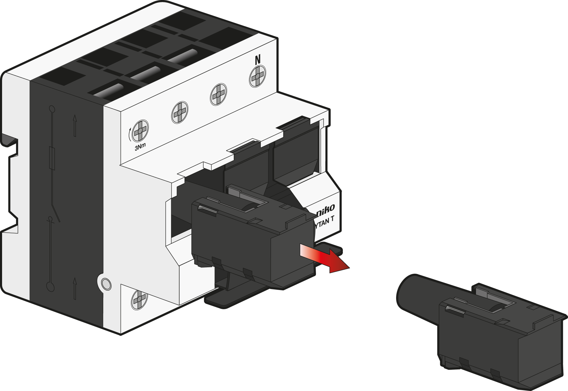
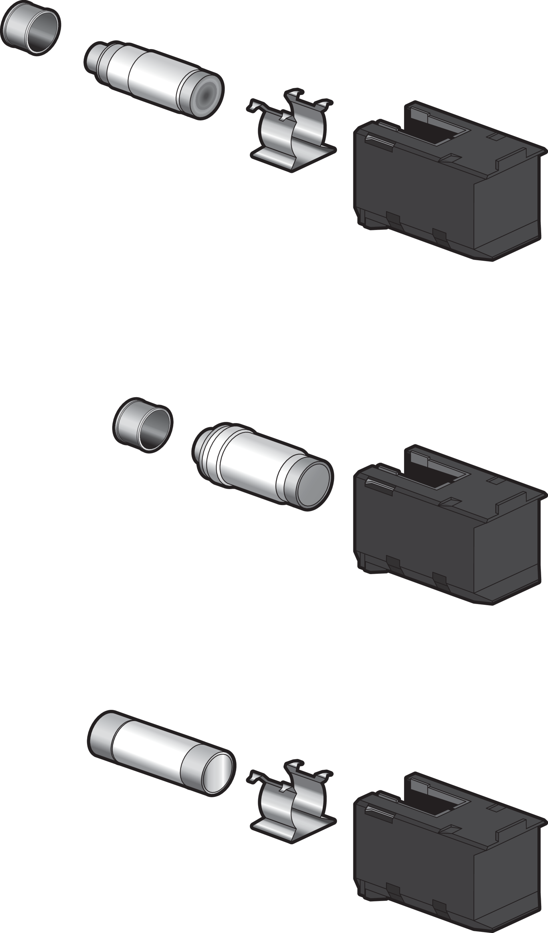
Remove the placeholder and insert the fuse link. Depending on the chosen fuse link, use the appropriate spacers:
Step 5
Switch ON.
Step 6
If you have connected the main protecting relay, the yellow LED will start blinking.
Press the reset button on the main protecting relay for 5 seconds, until the 3 green LEDs light up:
|
LED status |
Icon |
Switch status |
|---|---|---|

|

|
|
|
|
|
|
|
|

|

|
Step 7
Check the fuse within 24 hours after switching ON:
-
The average operation temperature must be less or equal to 35 °C.
-
The terminals must remain secured at 3 Nm.