The installation should be carried out by a qualified installer and in accordance with the regulations of the local distribution system operator.
Step 1
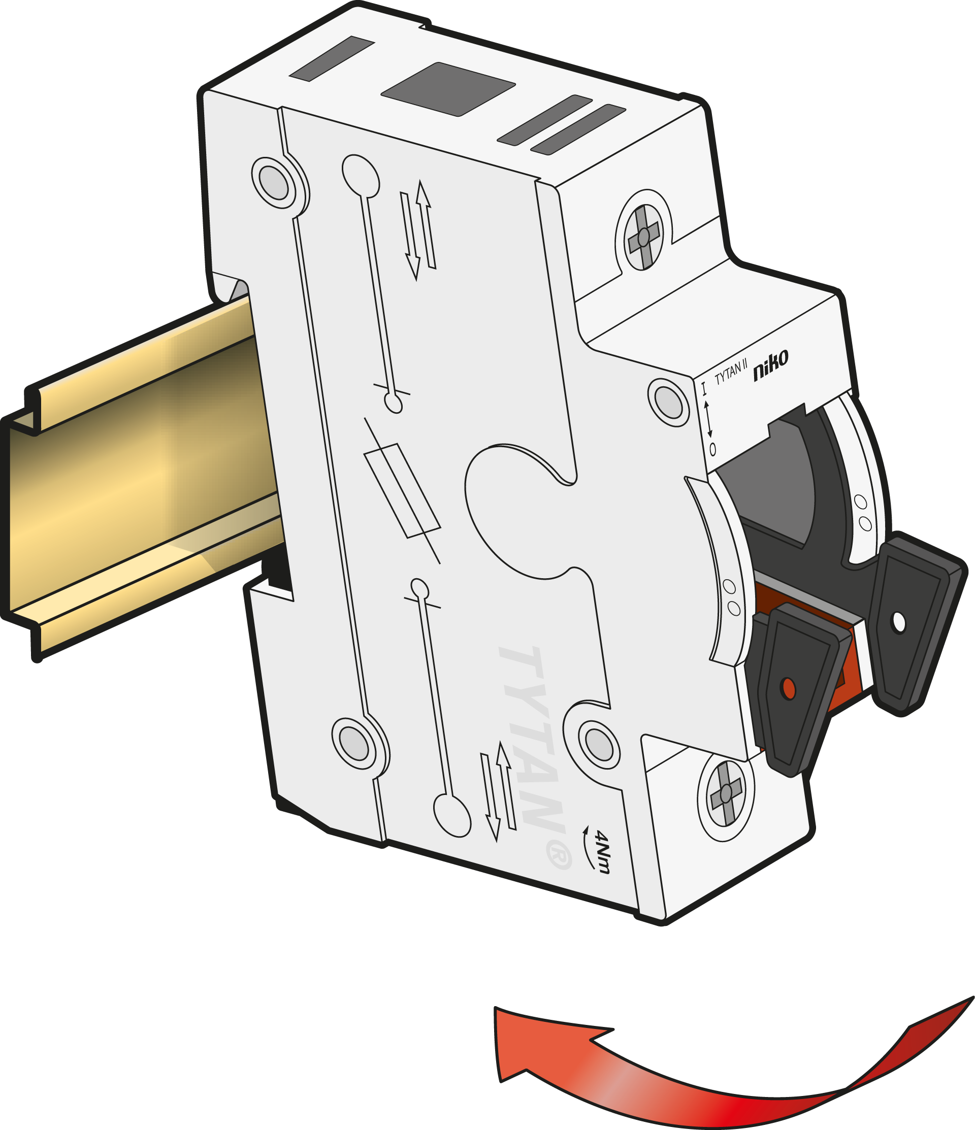
Click onto the DIN rail, according to IEC/EN 60715.
-
Pay attention to the rated diversity factor (RDF) according to IEC/EN 61439-1.
-
It is recommended to mount a box with fuse plugs on the DIN rail next to the fuse(s), to make spare fuse plugs readily available. Replacing a blown fuse plug with a spare one avoids touching the hot fuse.
Step 2
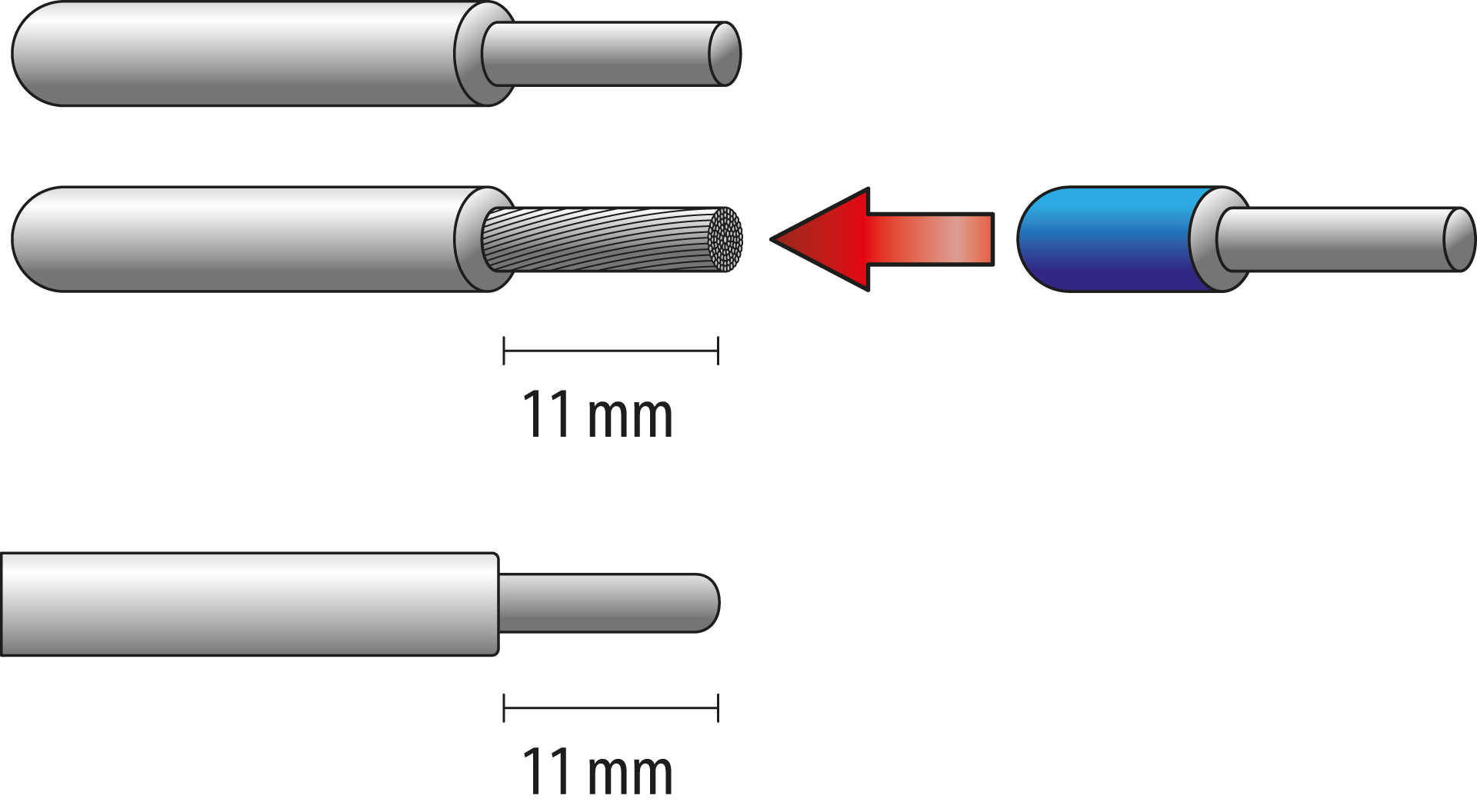
Only use suitable wires:
-
Copper
-
Rigid, stranded or flexible
-
Cross section 1,5 – 35 mm2
Strip the wires. Use ferrules for flexible wires.
Step 3
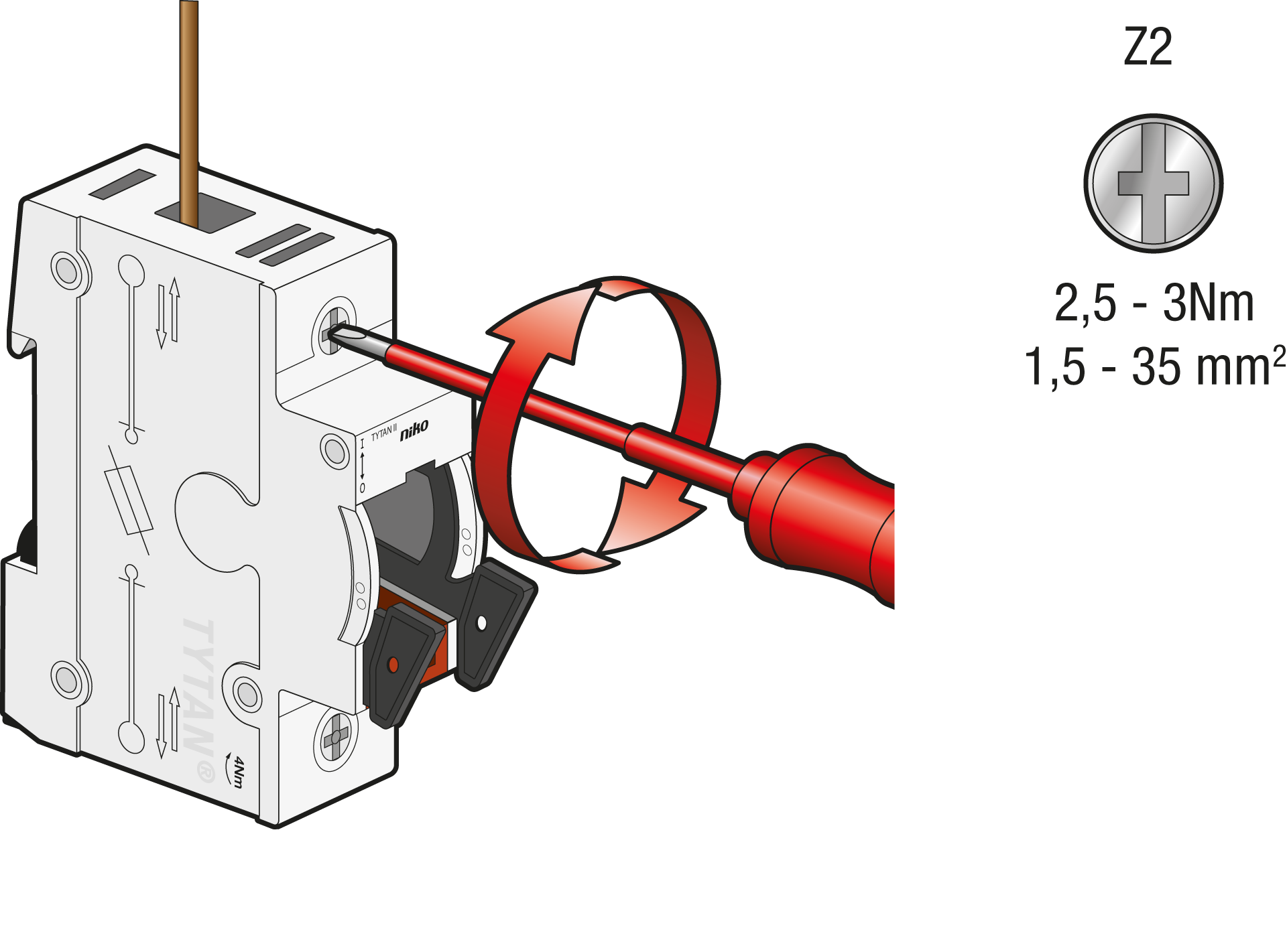
Feed the main wires at the top or at the bottom of the fuse switch disconnector, and the consumption at the opposite side. Secure with 3 Nm, using a PZ2 screw driver.
Use the wiring diagram to connect the wires correctly.
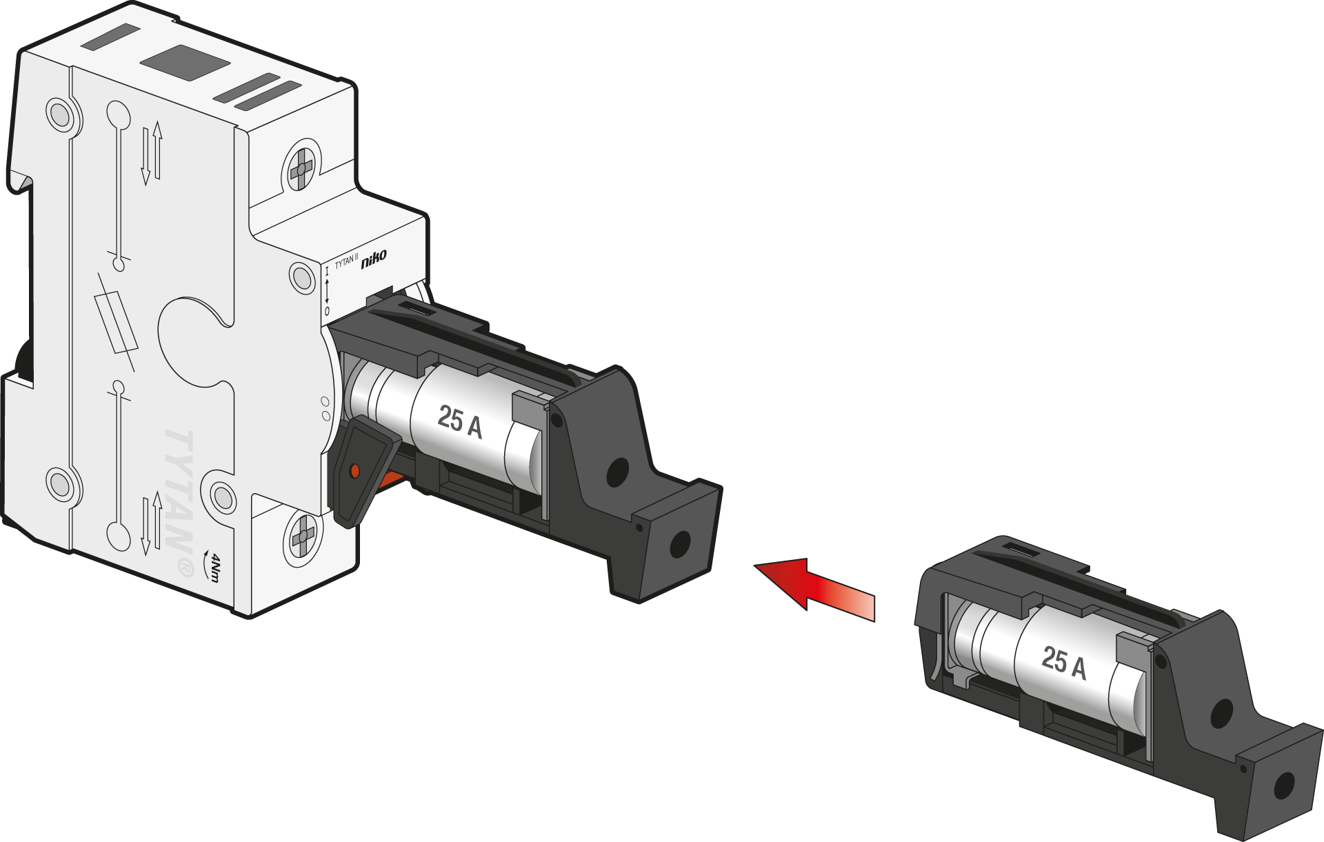
Step 4
a. Place an indicator of the correct colour according to the fuse link that is used.
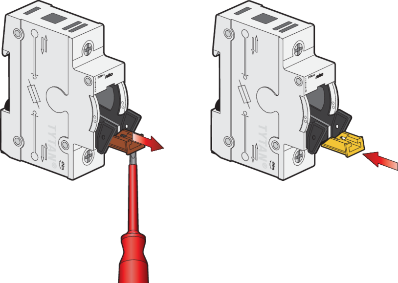
b. Insert the fuse link in the fuse plug.
|
Reference code |
Fuse link |
Colour coding |
|
|---|---|---|---|
|
2 A |

|
Pink |
|
|
4 A |

|
Brown |
|
|
6 A |

|
Green |
|
|
961-9130300 | TYTAN® II fuse plugs with LED indication 3x10A |
10 A |

|
Red |
|
961-9200300 | TYTAN® II fuse plugs with LED indication 3x13A |
13 A |

|
Black |
|
961-9140300 | TYTAN® II fuse plugs with LED indication 3x16A |
16 A |

|
Grey |
|
961-9150300 | TYTAN® II fuse plugs with LED indication 3x20A |
20 A |

|
Blue |
|
961-9160300 | TYTAN® II fuse plugs with LED indication 3x25A |
25 A |

|
Yellow |
|
961-9220300 | TYTAN® II fuse plugs with LED indication 3x32A |
32 A |

|
Violet |
|
961-9170300 | TYTAN® II fuse plugs with LED indication 3x35A |
35 A |

|
Black |
|
961-9230300 | TYTAN® II fuse plugs with LED indication 3x40A |
40 A |

|
Green |
|
961-9180300 | TYTAN® II fuse plugs with LED indication 3x50A |
50 A |

|
White |
|
961-9190300 | TYTAN® II fuse plugs with LED indication 3x63A |
63 A |

|
Copper |
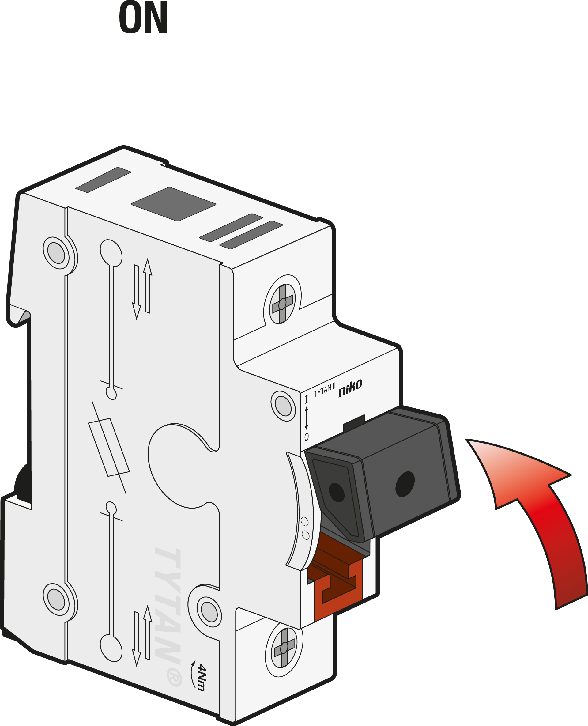
Step 5
Switch ON.
Step 6
Check the fuse within 24 hours after switching ON:
-
The average operation temperature must be less or equal to 35 °C.
-
The terminals must remain secured at 3 Nm.