What do you need?
Niko requirements
Your Niko Home Control installation meets the following requirements:
-
It has a connected controller II.
-
It is configured with the most recent programming software.
You need the following additional Niko product(s):
-
Optionally, a Digital black to control the HVAC system via a wall-mounted display
Daikin requirements
Your system meets the following requirements:
-
It is a VRV or VRF HVAC system.
-
The complete HVAC system is from the same brand.
Wiring diagram
For more information and complete installation instructions, consult the hardware manual of the HVAC interface (CoolMaster)
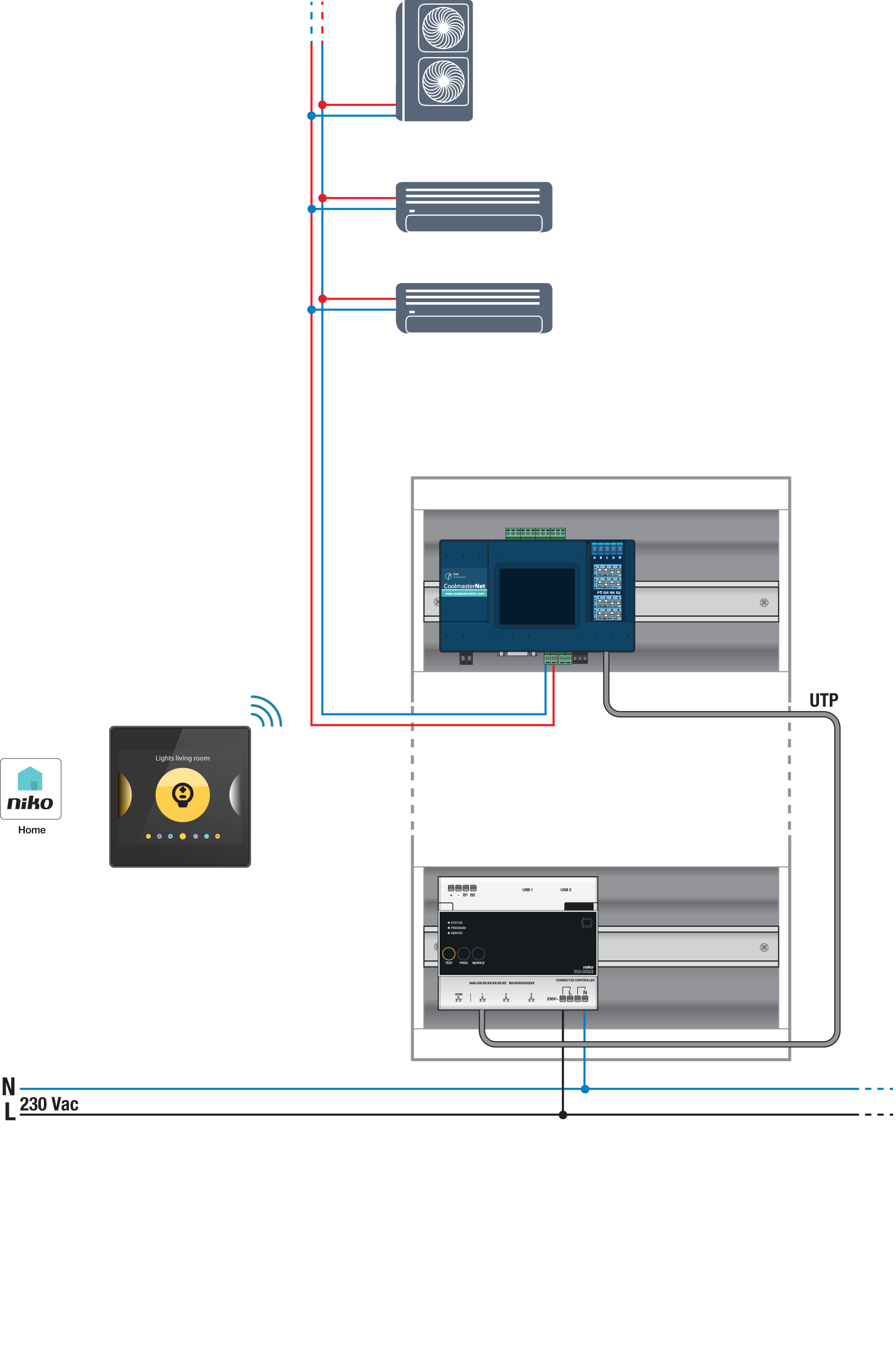
Bus connections on Daikin indoor unit: F1, F2
Programming
Configure the CoolMaster via the Niko Home Control programming software. Create a virtual HVAC thermostat for each zone and link it to the indoor unit(s) using the routine HVAC per thermostat; see https://guide.niko.eu/en/smnhc2/lv/hvac-per-thermostat.
After uploading the new configuration, the virtual HVAC thermostat(s) will appear in your Niko Home app in the Control tab. By editing this control, you can easily adjust the default settings for various programs and modes.