What can you do with CDVI and Niko Home Control?
If you connect a keypad or MiFare reader to Niko Home Control, you can use it to control other connected devices.
If you have already connected your garage doors or gates, you can, for example, open/close garage doors or gates by entering your personal code or by using a badge.
What do you need?
Niko requirements
Your Niko Home Control installation meets the following requirements:
-
It has a wireless smart hub or a connected controller II.
-
It is configured with the most recent programming software.
Depending on the basic modules of your Niko Home Control installation, you need to install the following additional products:
|
|
Required additional products |
Reference numbers |
|---|---|---|
|
Connected controller |
Digital potential-free sensor module If the output contact on your third-party device is not potential-free, you need an additional potential-free contact module (e.g. Finder 22.32.0.230.1xx0 for 230 V connections, Finder 22.32.0.012.1xx0 for 12 V DC connections, Finder 22.32.0.024.1xx0 for 24 V DC connections) |
|
|
Connected controller with a wireless bridge |
Connected switch or Connected dimmer control If the output contact on your third-party device is not 230 V, you need an additional 230 V contact module (e.g. Finder 22.32.0.230.1xx0 for potential-free connections, Finder 22.32.0.012.1xx0 for 12 V DC connections, Finder 22.32.0.024.1xx0 for 24 V DC connections) The connected (double) switch can be placed on a DIN rail using a modular holder (e.g. Legrand 412950) |
|
|
Wireless smart hub |
Connected switch or Connected dimmer control If the output contact on your third-party device is not 230 V, you need an additional 230 V contact module (e.g. Finder 22.32.0.230.1xx0 for potential-free connections, Finder 22.32.0.012.1xx0 for 12 V DC connections, Finder 22.32.0.024.1xx0 for 24 V DC connections) The connected (double) switch can be placed on a DIN rail using a modular holder (e.g. Legrand 412950) |
CDVI requirements
Don’t forget to mount the varistor.
Your system meets the following requirements:
-
It is a keypad and/or MiFare reader, installed in the proximity of the garage door or gate that you want to control.
-
Your system has a potential-free or 12/24 V DC or 230 V AC output contact.
Your system is one of the following CDVI products*:
|
|
Normally closed |
Normally opened |
|---|---|---|
|
Potential-free or 12/24 V DC contact |
|
|
*Consult the website of the supplier for detailed specifications and the latest products.
Wiring diagrams
The contacts of all CDVI products can be potential-free or 12/24 V DC, depending on the connected lock and the power supply. Check the details of your specific system before you connect it to the Niko modules.
Check the manual when using a Normally Closed circuit. Use the following contacts on the CDVI system for Normally Open circuits:
|
|
Contact 1 |
Common |
|---|---|---|
|
CAASE |
T1 |
C1 |
|
DGA |
Orange wire |
Pink wire |
|
KCINBT
|
Pin NO of the connector DOORx on the “separate control module” |
Pin C of the connector DOORx on the “separate control module” |
|
PROFIL100EINT |
Brown wire |
Yellow wire |
Connecting the sensor module
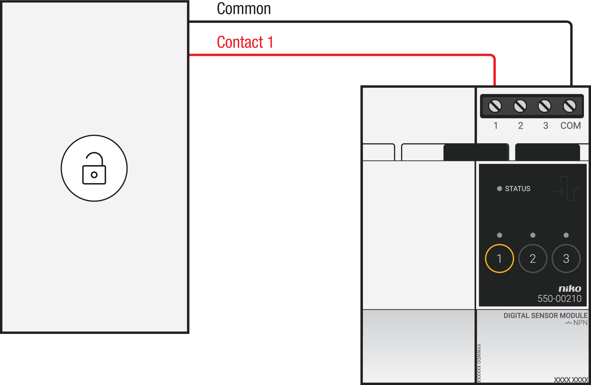
Via potential-free output contact
Connect contact 1 on the Niko sensor module to the output on the third-party system, as shown in the wiring diagram.
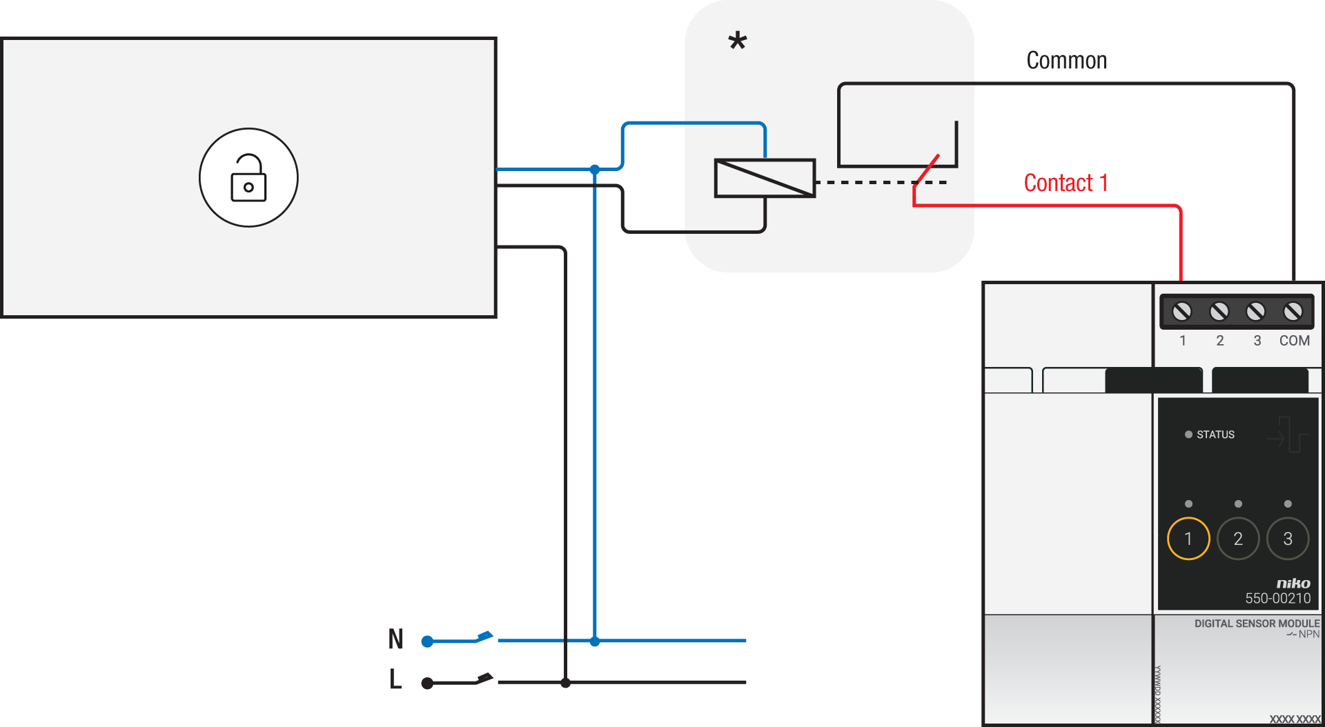
Via 230 V or 12/24 V output contact
If the contacts of your Keypad or MiFare reader are not potential-free, you additionally need an appropriate potential-free contact module.
Connect contact 1 on the Niko sensor module to the output on the third-party system, as shown in the wiring diagram.
|
230 V output contact |
12/24 V output contact |
|---|---|
*230 V to potential-free contact module (e.g. Finder 22.32.0.230.1xx0) |
*12 V to potential-free contact module (e.g. Finder 22.32.0.012.1xx0) or 24 V to potential-free contact module (e.g. Finder 22.32.0.024.1xx0) |
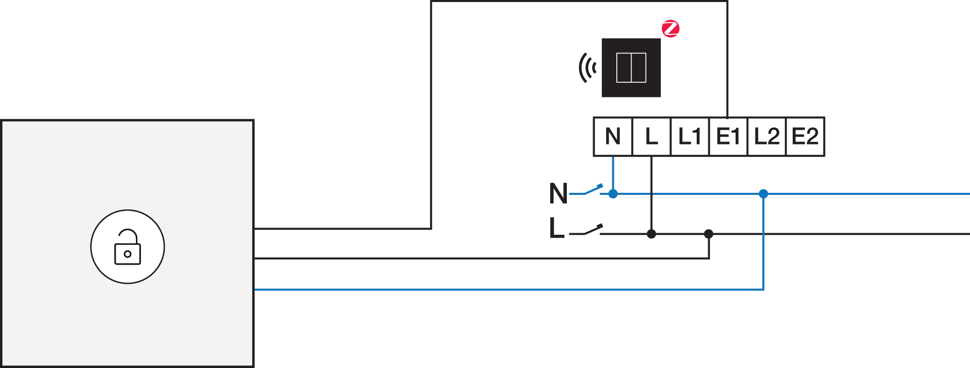
Connecting the connected switch
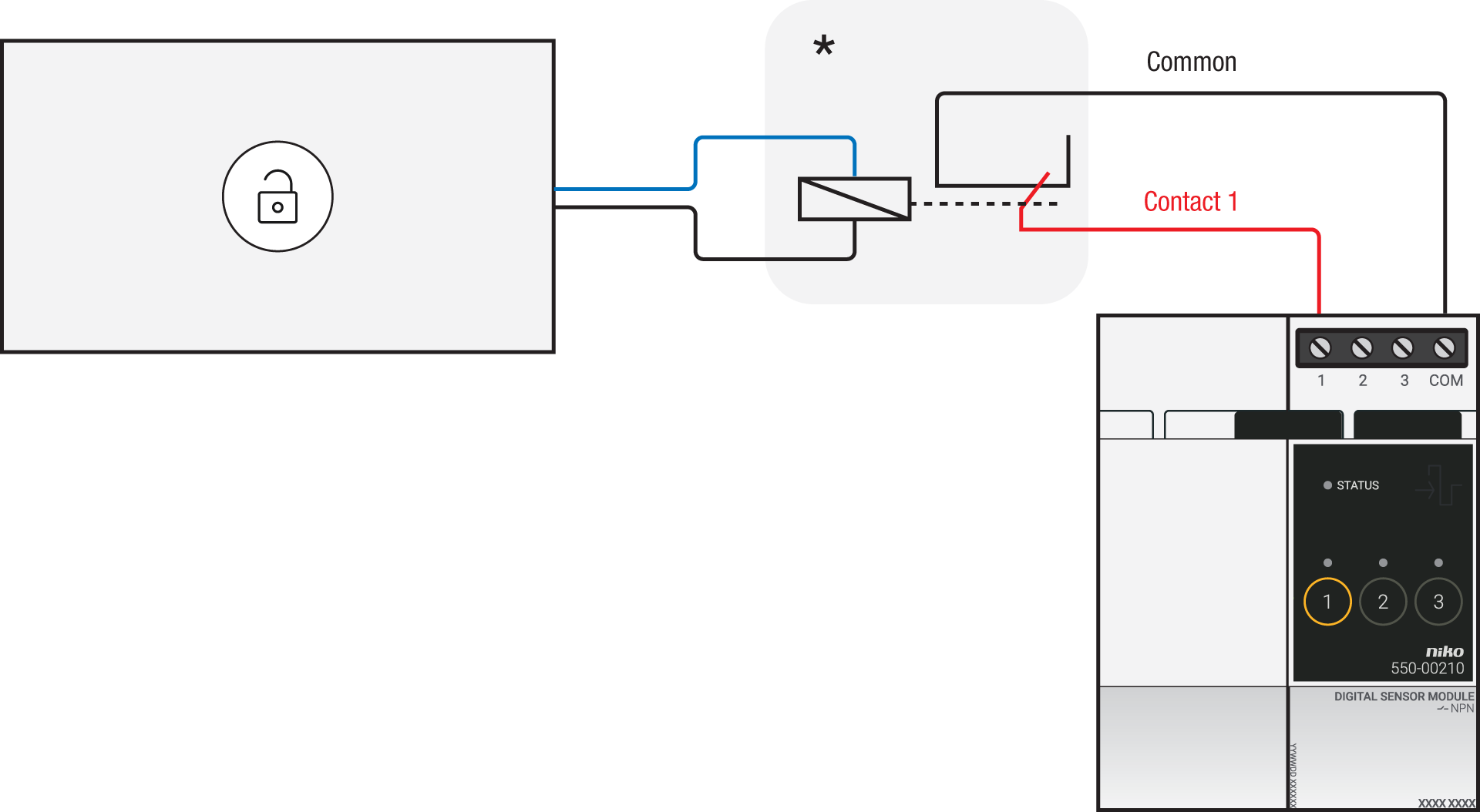
Via potential-free output contact
If the contacts of your Keypad or MiFare reader are not 230 V, you additionally need an appropriate potential-free contact module.
Connect contact 1 on the Niko connected switch to the output on the third-party system, as shown in the wiring diagram.
*230 V to potential-free contact module (e.g. Finder 22.32.0.230.1xx0)
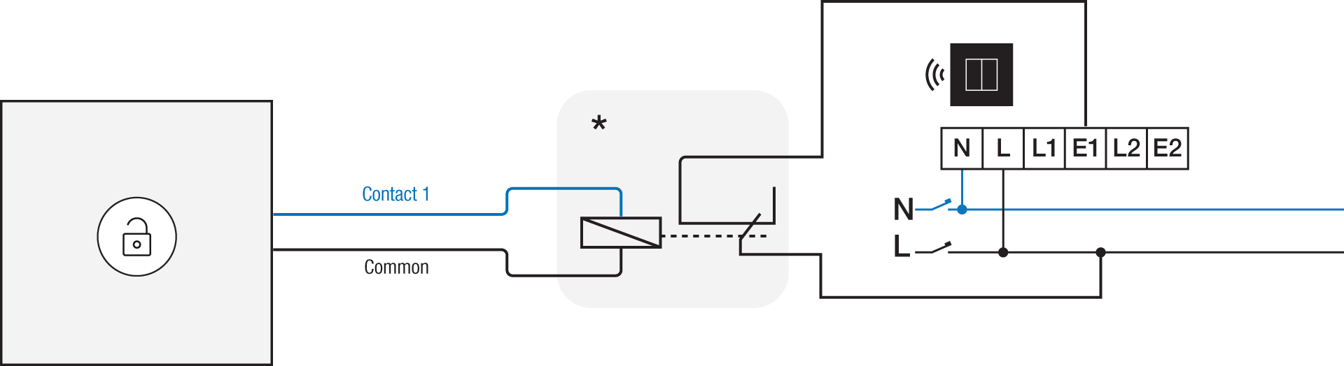
Via 230 V or 12/24 V output contact
If the contacts of your Keypad or MiFare reader are not 230 V, you additionally need an appropriate contact module.
Connect contact 1 on the Niko connected switch to the output on the third-party system, as shown in the wiring diagram.
|
230 V output contact |
12/24 V output contact |
|---|---|
|
*12 V to 230 V contact module (e.g. Finder 22.32.0.012.1xx0) or 24 V to 230 V contact module (e.g. Finder 22.32.0.024.1xx0) |
Programming
Check if your keypad or MiFare reader is normally open or normally closed.
Consult the programming instructions for your specific garage door and/or gate.
Configure the potential-free sensor module or connected switch and use its signal to trigger the garage doors and gates via the Niko Home Control programming software:
In case of bus wiring
-
Create a connection to external system.
-
Use the the inversion setting in case your keypad or MiFare reader is normally closed.
-
Create a condition, where the IF part is the connection to external system.
-
Use the THEN part to trigger your garage door or gate.
In case of traditional wiring
-
Assign the push-button extension to the extension button input (E1) of the connected switch.
-
Set the operating mode of the push-button extension on “push-button mode”.
-
Create a virtual device.
-
Link a basic action between the push-button extension and the virtual device.
-
Create a condition, where the IF part is the virtual device.
-
Use the THEN or ELSE part to trigger your garage door or gate:
-
Use the THEN part in case your keypad or MiFare reader is normally open.
-
Use the ELSE part in case your keypad or MiFare reader is normally closed.
-