What do you need?
Niko requirements
Your Niko Home Control installation meets the following requirements:
-
It has a wireless smart hub or a connected controller II.
-
It is configured with the most recent programming software.
Depending on the basic modules of your Niko Home Control installation, you need to install the following additional products:
|
|
Required additional products |
Reference numbers |
|---|---|---|
|
Connected controller |
Switching module with one free output per signal that you want to use in Niko Home Control If the input contact on your third-party device is not potential-free, you need an additional potential-free contact module (e.g. Finder 22.32.0.230.1xx0 for 230 V connections, Finder 22.32.0.012.1xx0 for 12 V DC connections, Finder 22.32.0.024.1xx0 for 24 V DC connections) |
|
|
Connected controller with a wireless bridge |
Connected (double) switch with one free output (L) per signal that you want to use in Niko Home Control If the input contact on your third-party device is not 230 V, you need an additional 230 V contact module (e.g. Finder 22.32.0.230.1xx0) The connected (double) switch can be placed on a DIN rail using a modular holder (e.g. Legrand 412950) |
|
|
Wireless smart hub |
Connected (double) switch with one free output (L) per signal that you want to use in Niko Home Control If the input contact on your third-party device is not 230 V, you need an additional 230 V contact module (e.g. Finder 22.32.0.230.1xx0) The connected (double) switch can be placed on a DIN rail using a modular holder (e.g. Legrand 412950) |
Came requirements
Your system meets the following requirements:
-
It has a potential-free or 12/24 V DC or 230 V AC contact to control the motor.
-
It is compatible with the Niko module (see Niko requirements).
Your system is one of the following Came products*:
|
|
Potential-free contacts |
|---|---|
|
Garage doors |
|
|
Gates |
|
*Consult the website of the supplier for detailed specifications and the latest products.
Wiring diagrams
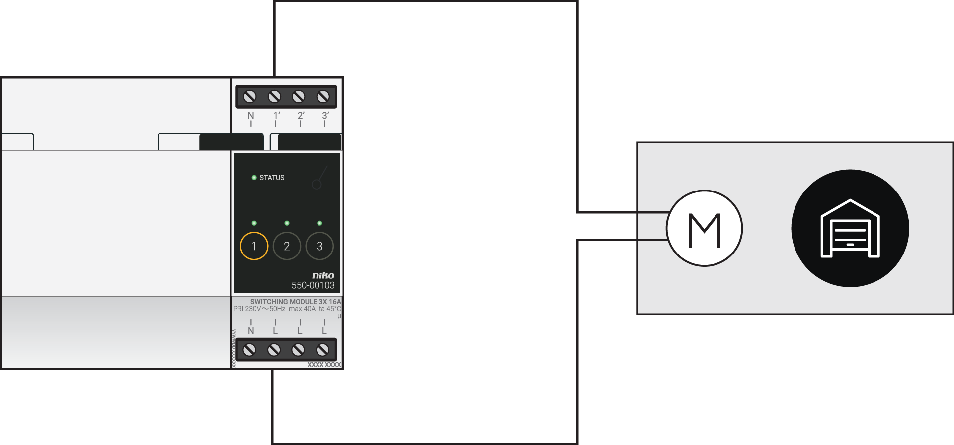
Connecting motors with a potential-free contact
|
Via the switching module |
Via the connected switch |
|---|---|
|
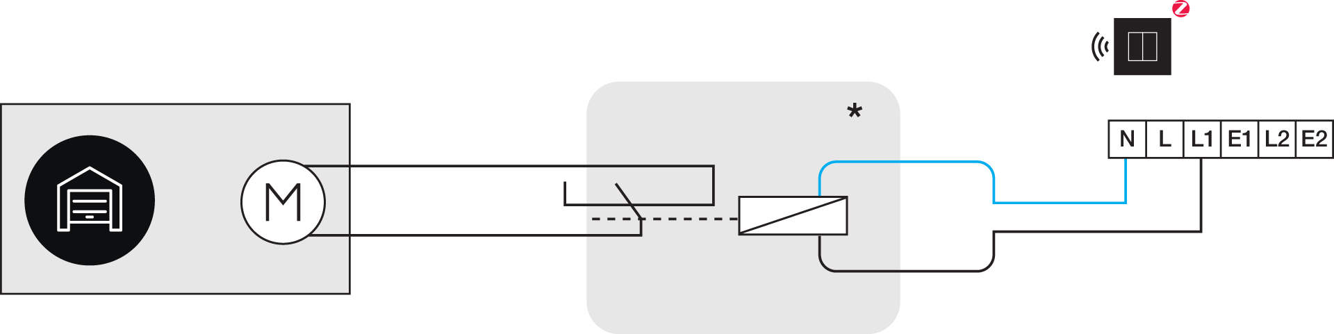
*230 V to potential-free contact module (e.g. Finder 22.32.0.230.1xx0)
|
Use the following contact F7 (command 2-7) on the Came product.
Programming
Configure the switching module or connected switch in the programming software. Depending on the type of installation, you can use the following instructions and programming examples as inspiration:
-
In case of bus wiring create a routine ‘Access control for motorised doors’, see https://guide.niko.eu/en/smnhc2/lv/access-control-for-motorized-doors
-
In case of traditional wiring create a pulse using a custom routine (define start and stop), see https://guide.niko.eu/en/penhc2/lv/creating-a-pulse-of-less-than-1-second-using-a-pus