Description
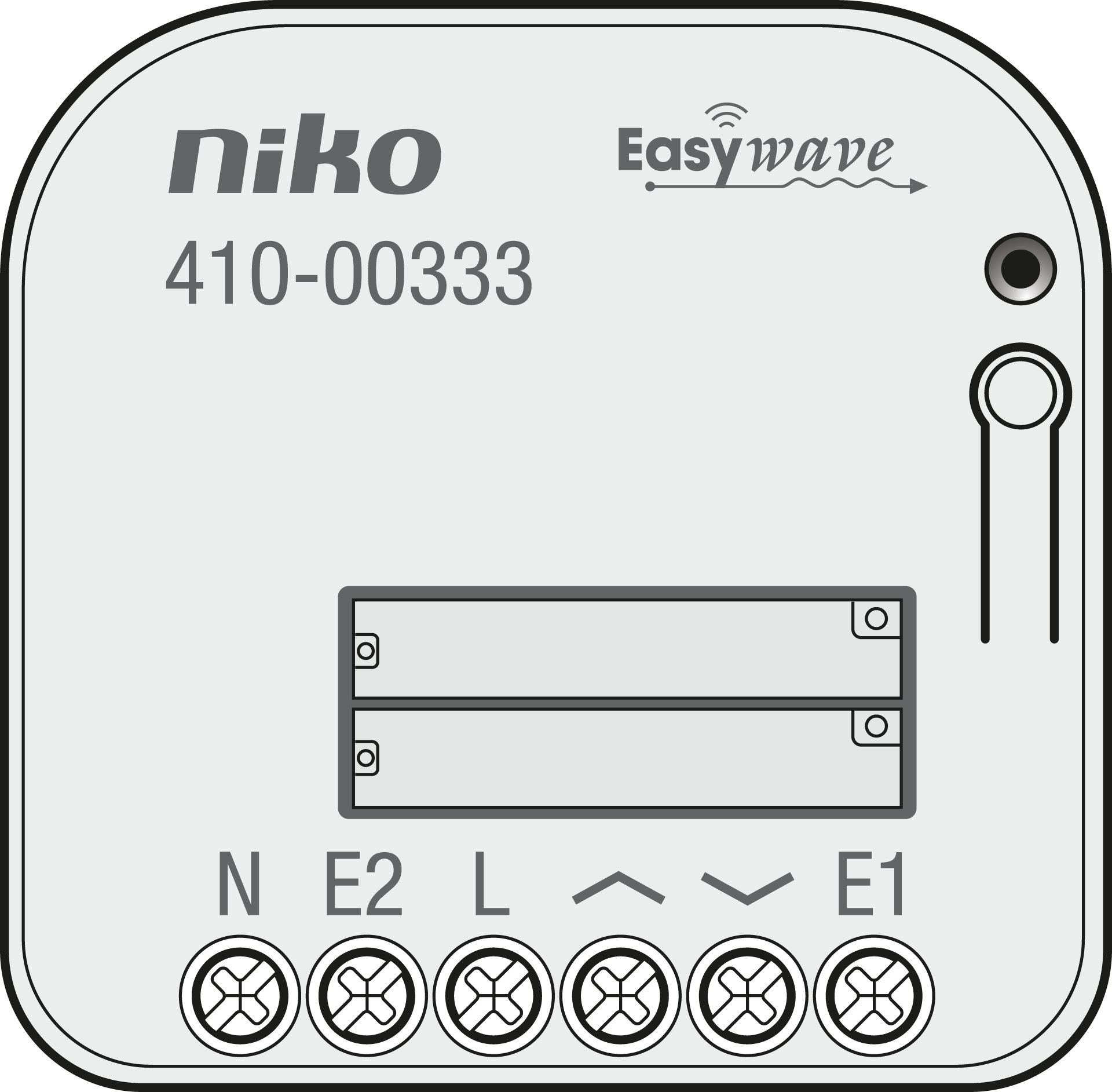
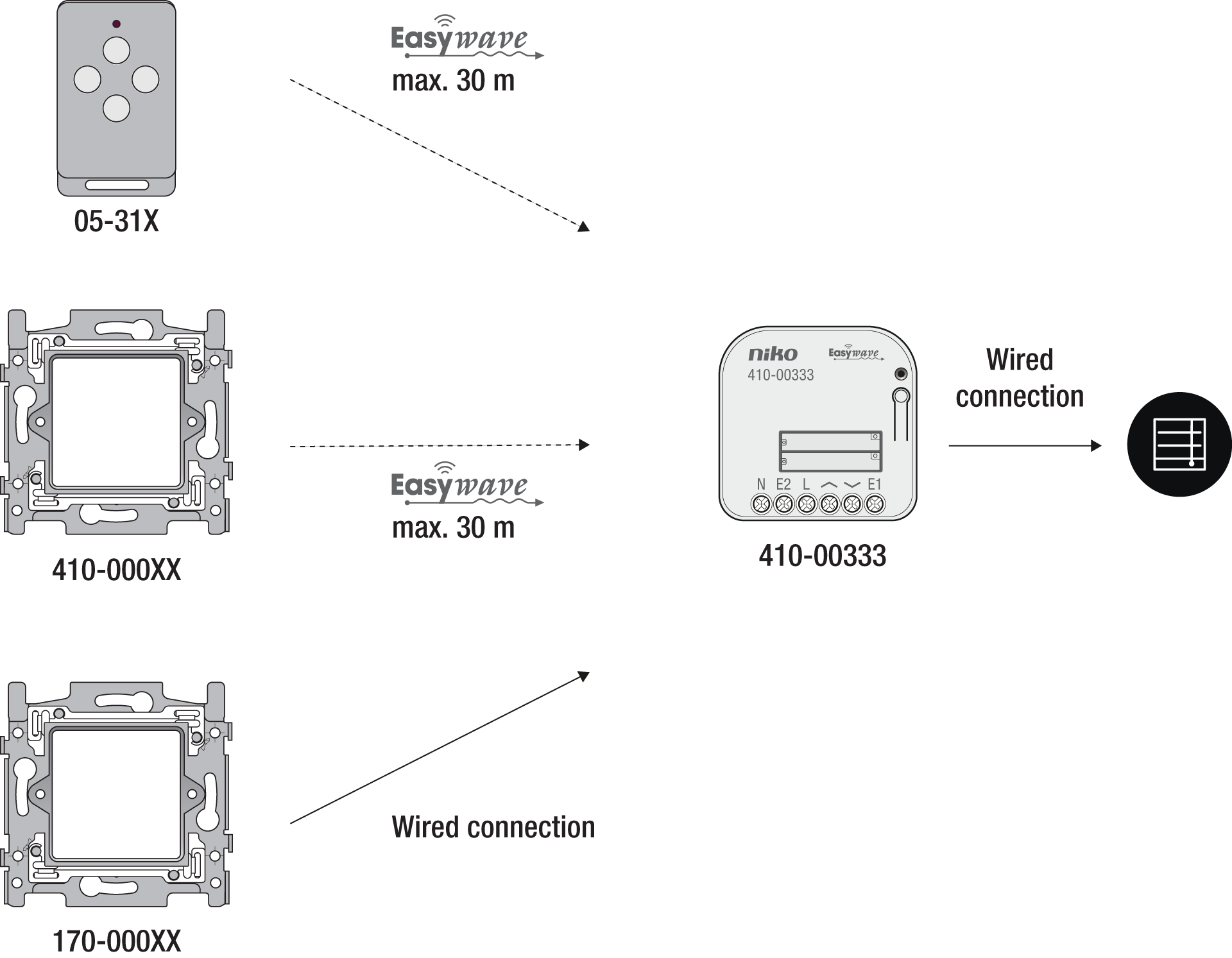
This flush-mounted receiver is used to open and close motor-controlled shutters and blinds using a wireless Easywave button or a wired button.This receiver has two 230 V normally open relay contacts, suitable to control a tubular motor.
Up to 32 transmission codes can be programmed into the receiver. The receiver is equipped with either 1-button operation (SEQUENCE), 2-button operation (UP/DOWN) or 3-button operation (UP/STOP/DOWN, optionally with slat adjustment for venetian blinds).
Compatible products
-
This product can be wirelessly controlled from a Niko Easywave hand-held transmitter (05-31X) and/or wireless push button (410-0000X). For local operation, external buttons can be connected.
-
This product can be installed behind a Niko blind plate (XXX-76900) or external wired push button (e.g. 170-0000X) in the colour of your choice.
-
This product is NOT compatible with Niko Home Control (550-XXXXX, 551-XXXXX, 552-XXXXX).
Installation
230 V – OFF
-
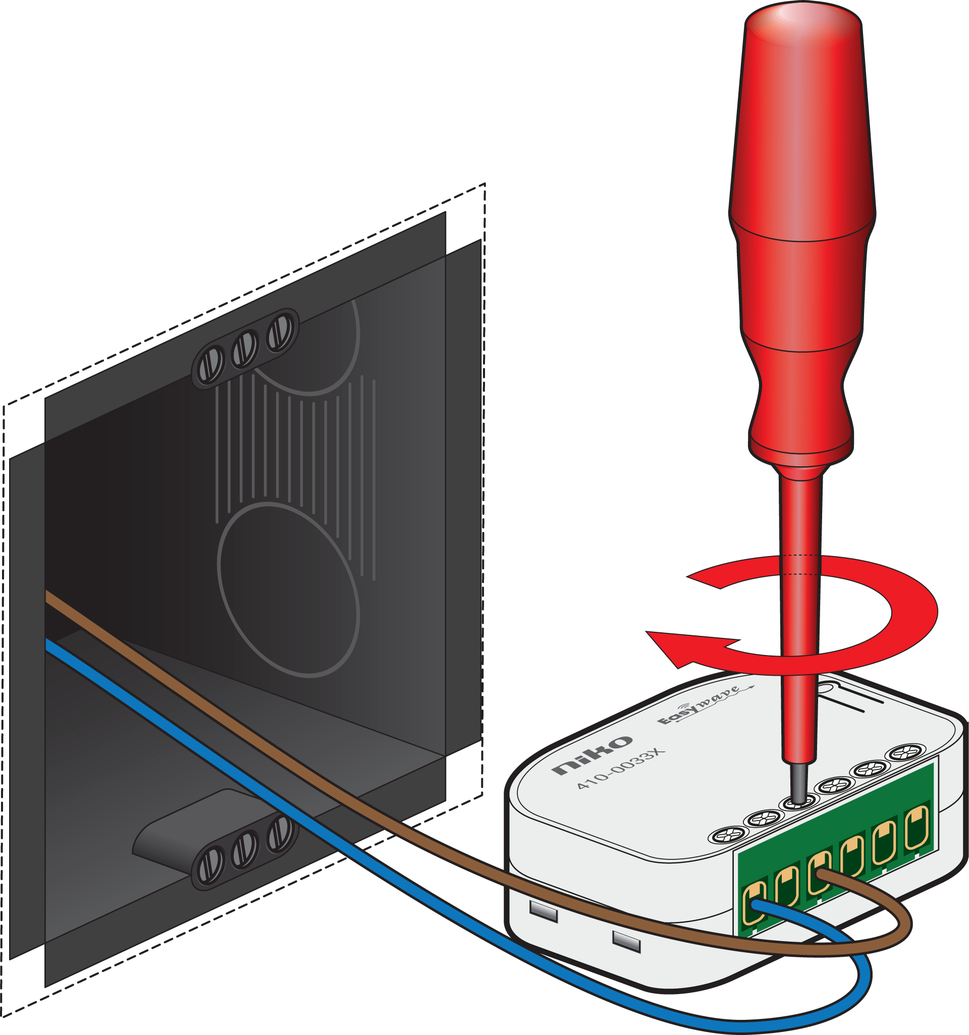
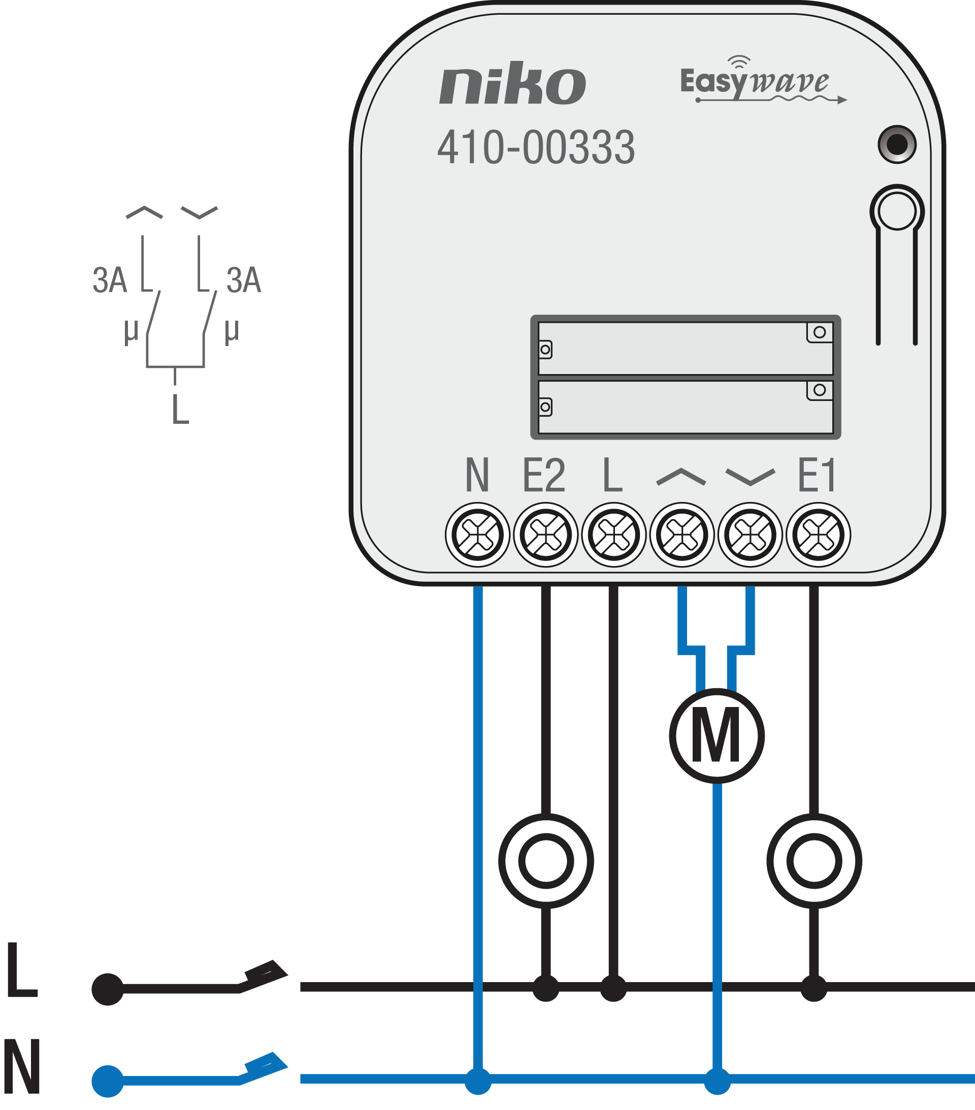
Connect the supply voltage and the devices to be controlled, according to the wiring diagram.
Only wires with a cable cross-section of 0.5 mm² to 2.5 mm² shall be connected.
The stripping length of the connecting wires is 6 to 7 mm.
230 V – ON
-
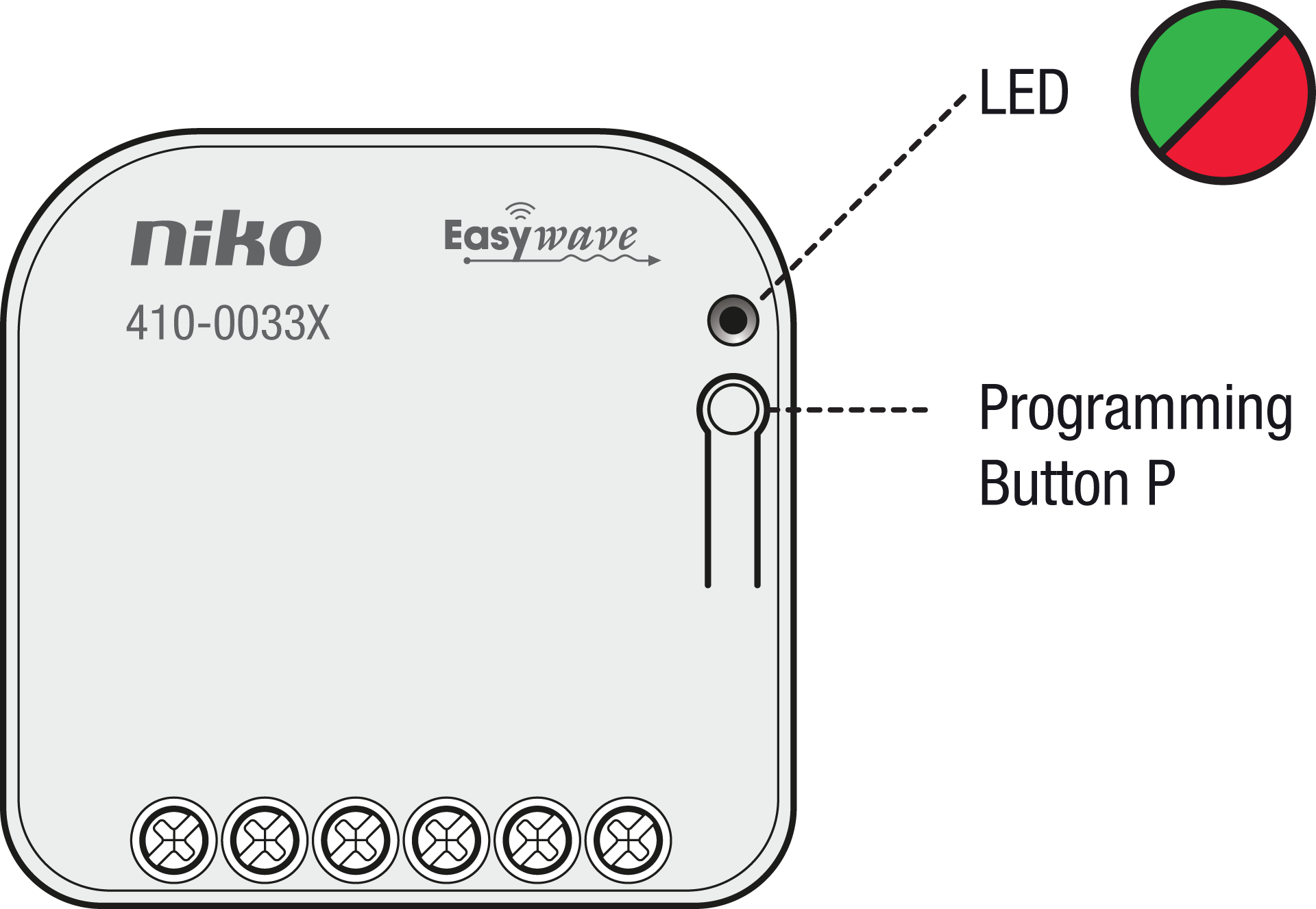
Complete the programming.
Button P and the LED on the receiver must be accessible during programming.
230 V – OFF
-
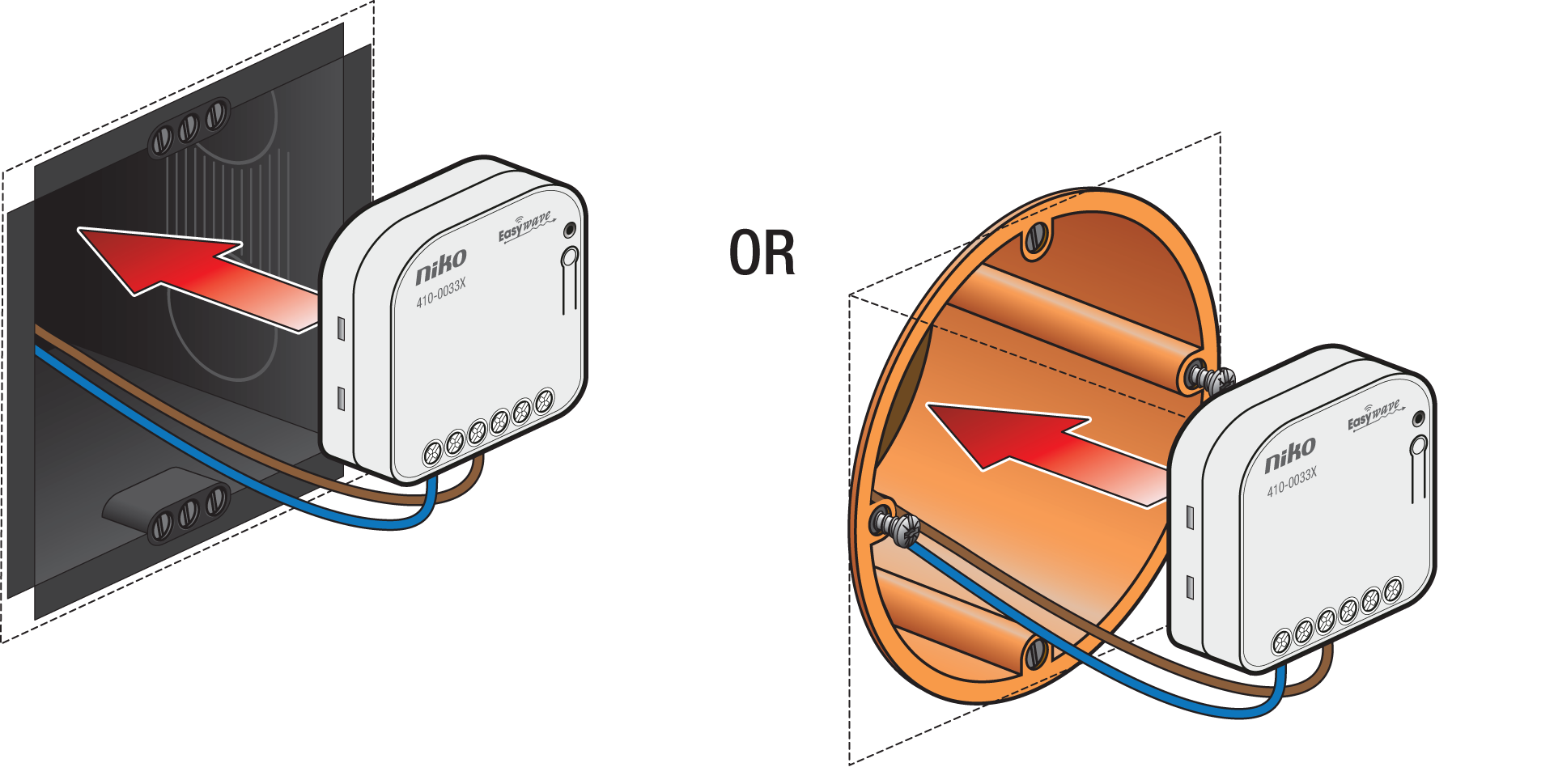
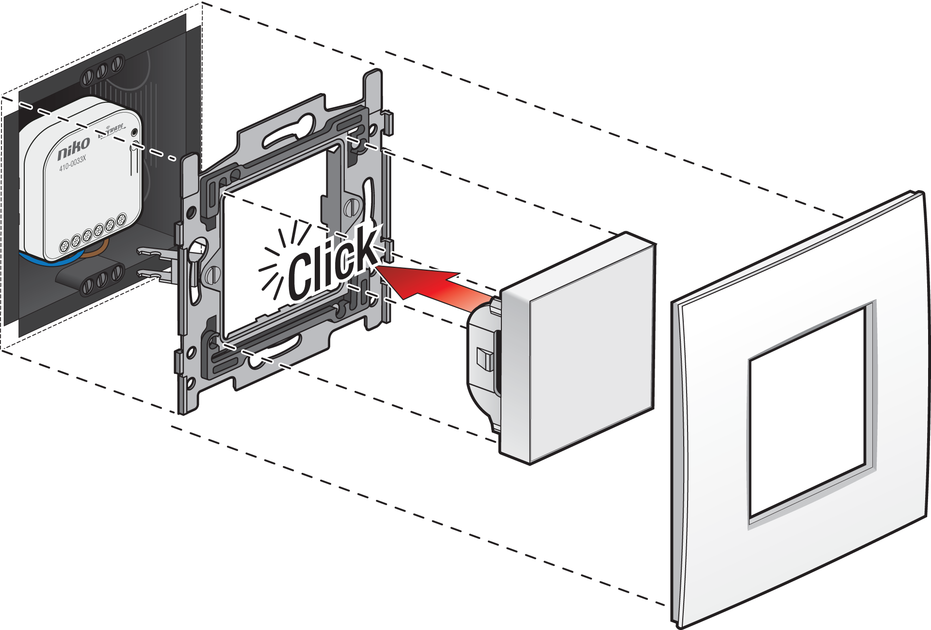
Place the receiver in the flush-mounting box.
-
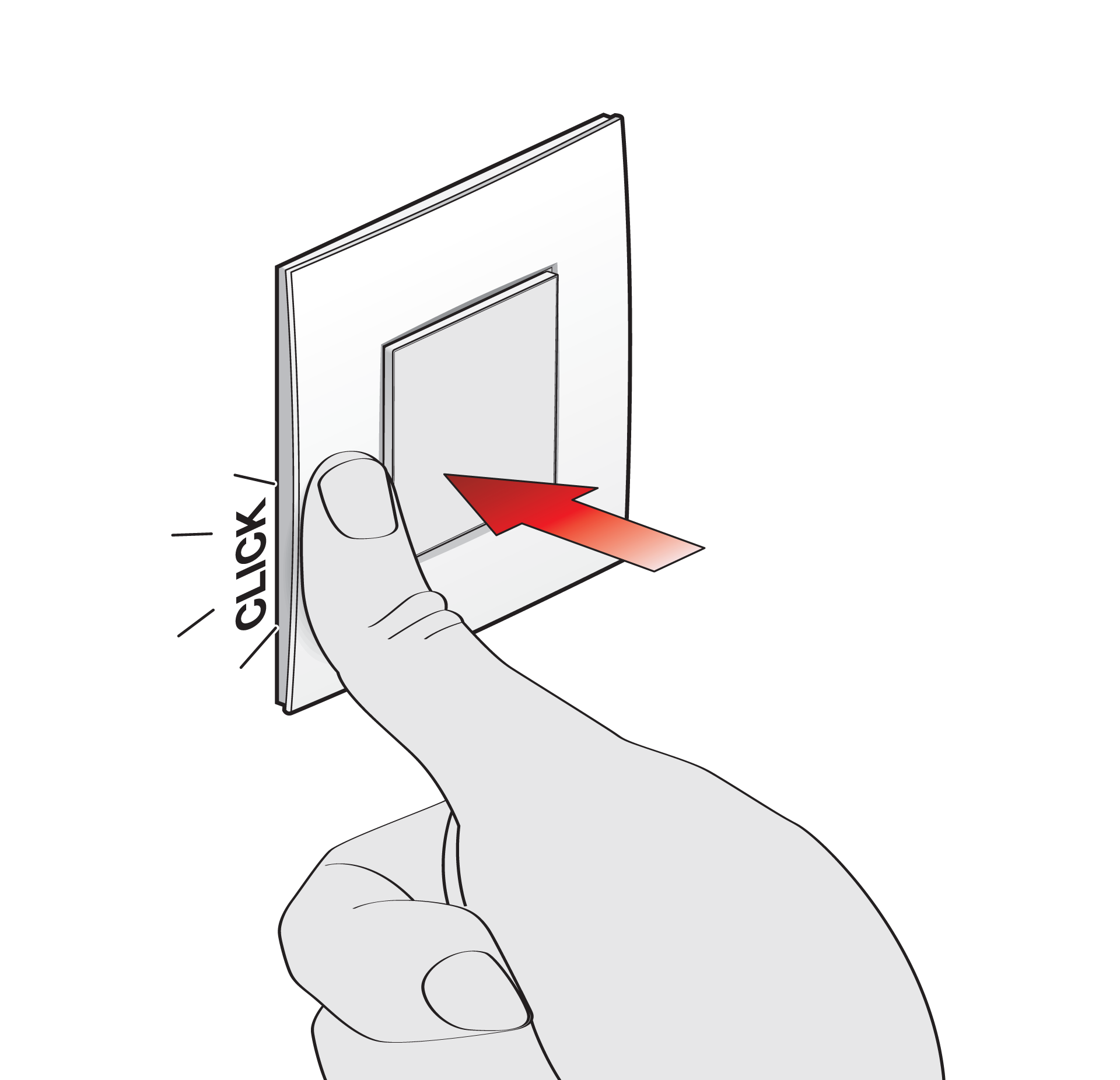
Mount the blind plate or push button.
|
|
Wiring
This product must be secured with a miniature circuit breaker (MCB) of max. 5 A in the electrical cabinet. The MCB rating is limited by national installation rules.
Operation and use
230 V – ON
Controlling via the push-button input (E1 + E2)
This product has two push-button inputs (E1 and E2), which have to be connected to L (see Wiring).
-
The push-button input E1 behaves like a transmitter button with button code A
-
The push-button input E2 behaves like a transmitter button with button code B
When used with factory settings, the push-button inputs work in the UP/DOWN 2-button operation mode without slat adjustment. The external buttons can be programmed in other operation modes or deleted at any time. If the external push-button is deleted from memory, the product returns to the factory settings.
-
In 1-button and 2-button operation, the movement command is carried out by briefly (< 2 s) pressing the connected buttons.
-
In 3-button operation, the buttons or switches must remain pressed for the desired period of movement. As long as the push-button input is active, no transmitter commands are accepted in the 3-button operation.
Controlling via wireless controls
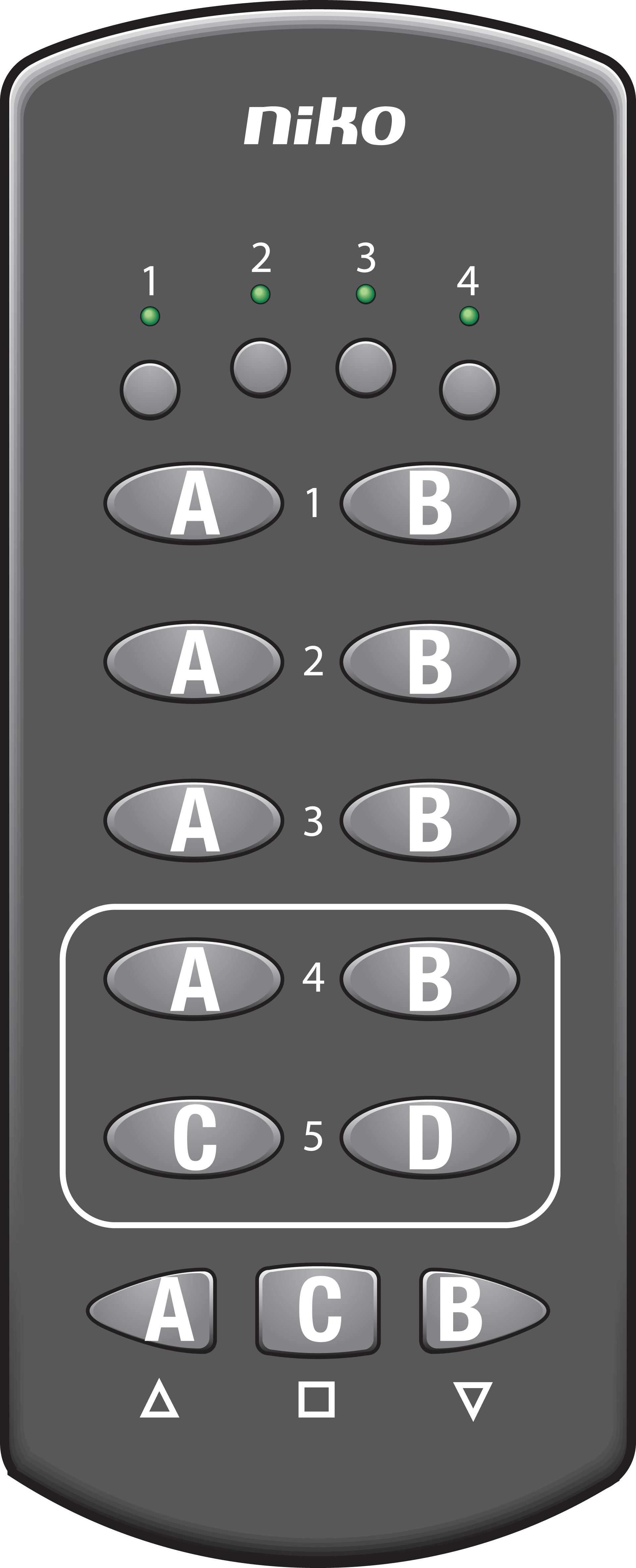
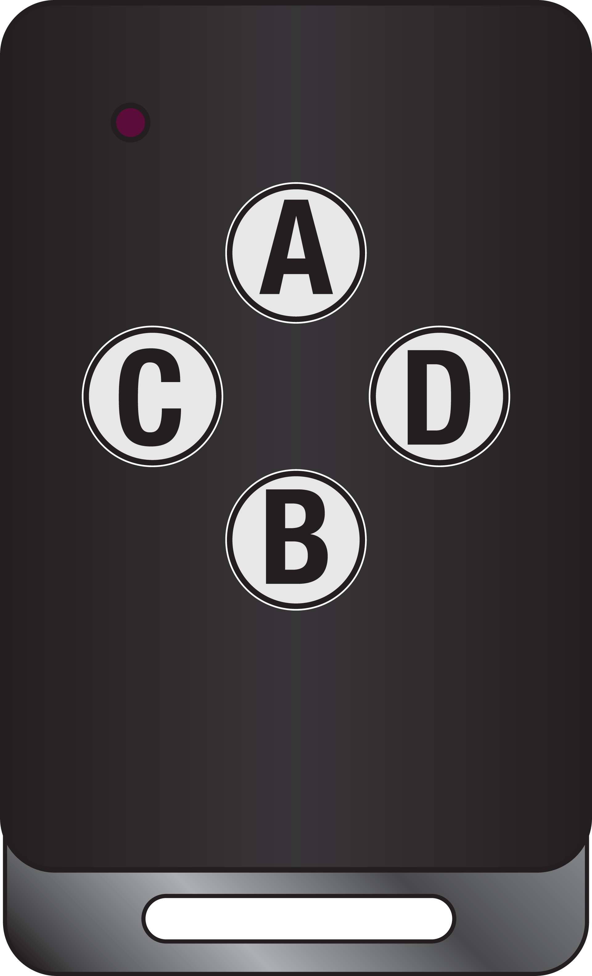
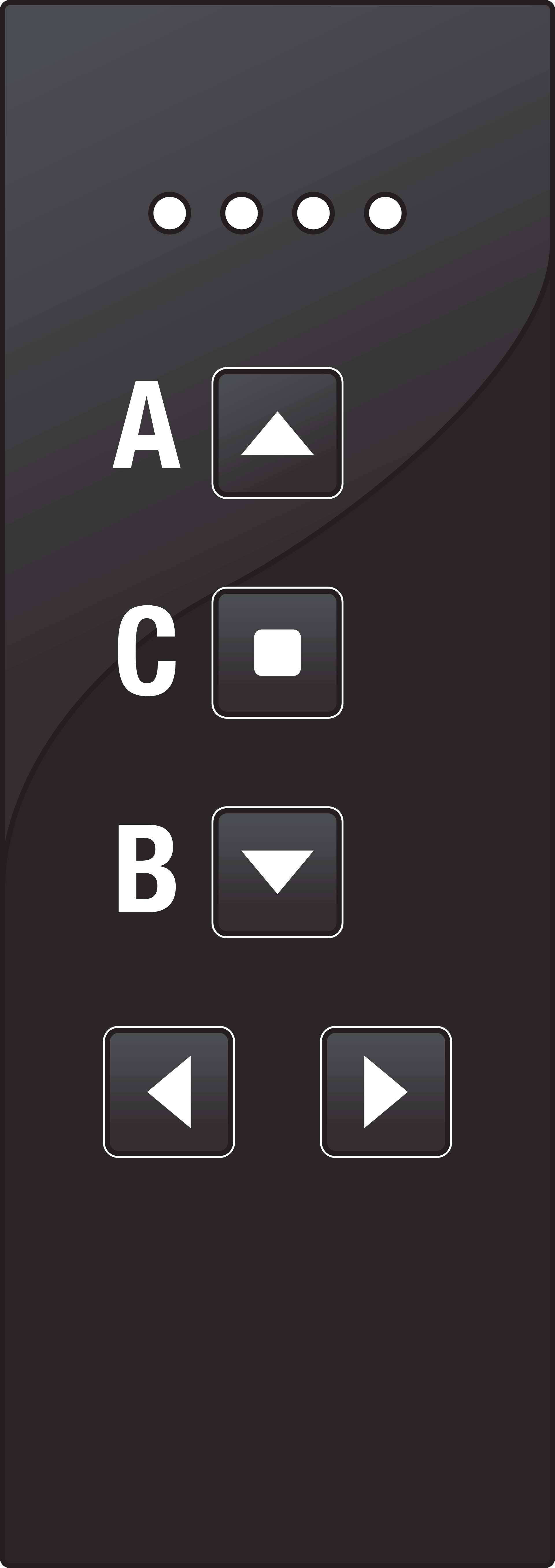
Each wireless push button, hand-held transmitter or external wired button can be assigned its own operation mode. You can use the following buttons:
|
05-311 |
05-312 |
05-317 |
05-318 |
410-00001 |
410-00002 |
|---|---|---|---|---|---|
|
|
|
|
|
|
Operation modes
When using the slat adjustment function, the motor is controlled in DEAD MAN mode for the first 2 seconds of transmitter actuation and only then switches to self-retaining.
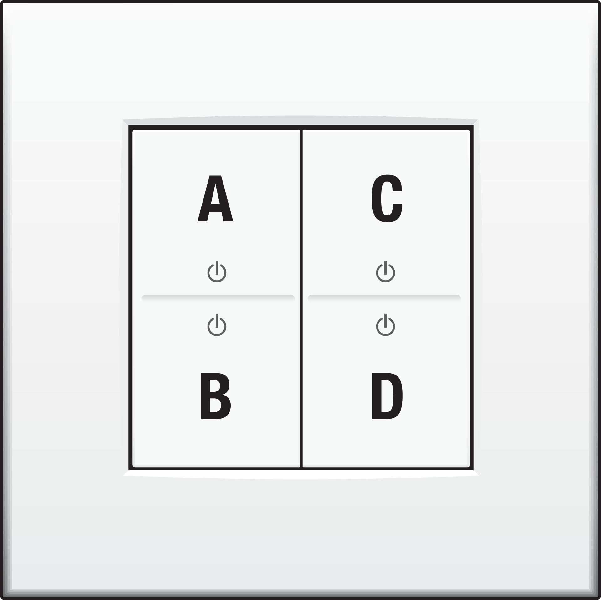
2-button operation
|
Operation mode |
Transmission code |
Command |
Other commands |
|---|---|---|---|
|
UP/DOWN
|
A or C |
Roller shutter UP |
STOP with opposite direction button Optionally with slat adjustment |
|
B or D |
Roller shutter DOWN |
3-button operation
|
Operation mode |
Transmission code |
Command |
Other commands |
|---|---|---|---|
|
UP/DOWN/STOP
|
A |
Roller shutter UP |
Optionally with slat adjustment |
|
C or D |
Roller shutter STOP |
||
|
B |
Roller shutter DOWN |
1-button operation
|
Operation mode |
Transmission code |
Command |
Other commands |
|---|---|---|---|
|
SEQUENCE |
A or B or C or D |
Roller shutter executes movement commands one after another: UP → STOP → DOWN → STOP → UP → … |
|
Programming
230 V – ON
Programming mode
With button P on the receiver, you can activate the programming mode for the required operation type on your receiver.
You can cancel the programming process by briefly pressing the P programming button maximum 3 times. Once the LED turns off, the receiver returns to standby.
If no button is pressed within 30 seconds, the receiver automatically switches to operation mode.
The settings are not saved.
Press the button to be programmed on the hand-held transmitter or the external button. The LED on the receiver provides feedback when the transmission code is programmed successfully.
When the LED on the receiver turns off, the receiver is ready for operation.
Entering programming mode
With short press (<2 seconds) and long press (>2 seconds), you can navigate through the programming structure. The LED on the receiver provides feedback on the selected programming mode, through its colour and the way it flashes.
Leaving programming mode
You can cancel the programming process by briefly pressing the P programming button maximum 3 times.
Setting 3-button operation modes
Only one transmitter button must be programmed, the code for the associated button is assigned automatically.
|
Desired operation mode |
Action |
Feedback LED
|
|
|---|---|---|---|
|
Without slat adjustment |
|||
|
UP/STOP/DOWN |
Step 1: on the receiver |
2x short press |
|
|
Step 2: on transmitter |
1x short press |
2 seconds |
|
|
With slat adjustment |
|||
|
UP/STOP/DOWN |
Step 1: on the receiver |
2x short press |
|
|
1x long press |
|
||
|
Step 2: on transmitter |
1x short press |
2 seconds |
|
Setting 2-button operation modes
Only one transmitter button must be programmed, the code for the associated button is assigned automatically.
|
Desired operation mode |
Action |
Feedback LED
|
|
|---|---|---|---|
|
Without slat adjustment |
|||
|
UP/DOWN |
Step 1: on the receiver |
1x short press |
|
|
Step 2: on transmitter |
1x short press |
2 seconds |
|
|
With slat adjustment |
|||
|
UP/DOWN |
Step 1: on the receiver |
1x short press |
|
|
1x long press |
|
||
|
Step 2: on transmitter |
1x short press |
2 seconds |
|
Setting 1-button operation modes
|
Desired operation mode |
Action |
Feedback LED
|
|
|---|---|---|---|
|
SEQUENCE |
Step 1: on the receiver |
3x short press |
|
|
Step 2: on transmitter |
1x short press |
2 seconds |
|
Setting the runtime
Runtime options
The runtime of the receiver outputs can be set separately for each movement direction. This protects the end position switches of a connected motor.
Each movement command received is carried out for the currently set runtime. This runtime applies to all programmed transmitters, even if the transmitters were already programmed before a measurement.
-
The default setting for the runtime is 90 seconds for both directions.
-
The maximum runtime that can be set is approximately 1.8 hours.
Runtime measurement
To be able to carry out a runtime measurement, at least one transmitter must be programmed into the receiver.
If you try to start the runtime measurement without at least one transmitter being programmed, the LED P flickers red for 4 seconds and the receiver switches back to operation mode.
To change the runtime setting, perform a runtime measurement as described in the steps below. You can repeat the procedure as often as you like, as long as the runtime measurement mode is active. The last measured runtime for each direction is saved.
If the runtime measurement was started with a transmitter, it must be completed with the exact same transmitter. Other transmitters are ignored for the duration of the measurement.
Make sure the roller shutter is completely open before you start the runtime measurement.
|
Desired operation mode |
Action |
Feedback LED
|
Note |
|
|---|---|---|---|---|
|
RUNTIME MEASUREMENT |
Step 1: on the receiver |
3x short press |
|
|
|
1x long press |
|
|
||
|
Step 2: on the transmitter |
Close the roller shutter completely. Send a STOP command, when the lower end position is reached. |
|
Give a STOP command as soon as the roller shutter has reached the end position (regardless of whether the roller shutter has already stopped independently). |
|
|
Step 3: on the transmitter |
Open the roller shutter completely. Send a STOP command, when the upper end position is reached. |
|
Give a STOP command as soon as the roller shutter has reached the end position (regardless of whether the roller shutter has already stopped independently). |
|
|
Step 4: on the receiver |
1x long press |
2 seconds |
Ends the runtime measurement and saves the values. |
|
The runtime measurement can be cancelled by briefly pressing the programming button P. This discards all currently measures values.
Deleting transmitters
In delete mode, individual transmitters can be specifically deleted from the memory of the receiver.
|
Action |
Feedback LED |
||
|---|---|---|---|
|
Step 1: Activate delete mode on receiver |
On the receiver |
1x long press |
|
|
Step 2: Delete transmitter |
On the transmitter |
1x short press |
2 seconds |
Resetting the receiver
Set the receiver back to the factory settings by doing a reset. All programmed transmitters are deleted and the runtime for both directions is reset to factory settings.
|
Action |
Feedback LED |
||
|---|---|---|---|
|
Step 1: Activate delete mode on receiver |
On the receiver |
1x long press |
|
|
Step 2: Delete transmission codes and restore the factory settings |
On the receiver |
1x long press |
4 seconds |
Troubleshooting
New installations
If the Easywave system does not work after being programmed, perform the following checks:
-
Check whether the shield between the battery and the contacts in the push button or hand-held transmitter has been removed.
-
Check whether there is good contact integrity between the battery and the battery contacts.
-
Check the operation of the connected receiver. Press the programming button (P) on the front of the receiver. If the status LED does not flash, the receiver is defective.
-
Check the operation of the push button. Take the hand-held transmitter and walk toward the receiver:
-
If the Easywave system works with the hand-held transmitter but not with the push button, it is possible that moisture or metal is present in the wall. Move the push button, or use a wireless Easywave repeater (05-535) to increase the range.
-
If the Easywave system works only at a short distance, the push button has been moved beyond the transmission range or there is a problem due to interference. Place the push button closer or outside of the range of the interference, or use a wireless Easywave repeater (05-535) to increase the range.
-
If the Easywave system does not work at all, even when you bring the hand-held transmitter close to the receiver, check the programming and/or the batteries of the hand-held transmitter.
-
Existing installations
In case of problems in an existing installation, check whether the surroundings of the Easywave system have changed, possibly causing interference (metal electricity cabinet, walls, moved furniture, etc.) Restore the original arrangement, if possible.
|
Problem |
Possible cause |
Proposed solution |
|---|---|---|
|
Lighting switches on automatically |
The Easywave system is switched on, because another push button or hand-held transmitter is programmed within the reception range |
Reset the receiver and reprogram |
|
Lighting switches off automatically |
The Easywave system is switched off, because another push button or hand-held transmitter is programmed within the reception range |
Reset the receiver and reprogram |
|
The Easywave system is switched off, due to a (brief) interruption in the power supply |
Switch the light back on using the programmed transmitter for this receiver |
|
|
Receiver does not respond to pressed buttons |
The battery of your wireless push button might be depleted after several years of use |
Check the battery of the wireless push button |
Wireless network
The operation of devices with a remote control, such as a TV or video and audio devices, is not disrupted by an Easywave hand-held transmitter. The hand-held transmitter does not have to be aimed towards the wireless Easywave receiver. The indoor range is ± 30 m. In open spaces the range reaches 100 m. The range of the hand-held transmitter depends on the materials used in the residence.
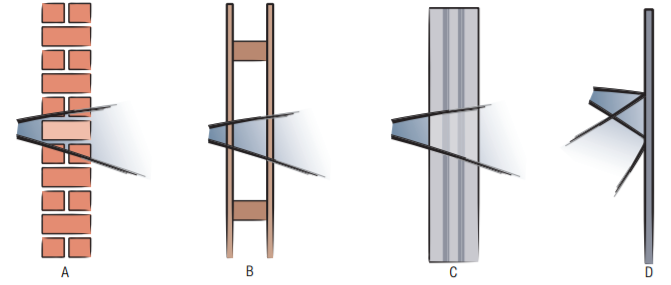
|
A |
Brick, concrete |
Loss of 20 to 40% |
|
B |
wood, plaster walls |
Loss of 5 to 20% |
|
C |
reinforced concrete |
Loss of 40 to 90% |
|
D |
confined metal space |
Loss of 90 to 100% |
A diagnostic device (05-370) can be used to determine the wireless signal strength in an environment. The appliance recognizes all 868.3 Mhz signals. The nine LEDs on the device will indicate the quality of the signals received or the strength of any interrupting signals. This allows you to determine whether or not the signal range of the hand-held transmitter will meet your needs.
Product information
This link takes you to the product page. There, you will find detailed specifications, all compatible articles, certificates of CE-marking, etc.
This online manual is applicable to the following product(s):
-
410-00333 | RF receiver for motor control, 230 V, 2 N.O. contacts, flush mounting
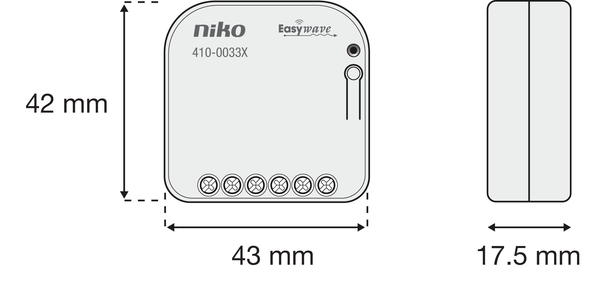
Dimensions
Disclaimer
Read the manual completely before installing and activating the system.
Niko prepares its manuals with the greatest care and strives to make them as complete, correct and up to date as possible. Nevertheless, some deficiencies may subsist. Niko cannot be held responsible for this, other than within the legal limits. Please inform us of any deficiencies in the manuals by contacting Niko customer services at support@niko.eu.
Legal information
Support & Contact
nv Niko sa
Industriepark West 40
9100 Sint-Niklaas, Belgium
+32 3 778 90 80
support@niko.eu
Warnings regarding installation

|
The installation of products that will permanently be part of the electrical installation and which include dangerous voltages, should be carried out by a qualified installer and in accordance with the applicable regulations. This user manual must be presented to the user. It should be included in the electrical installation file and it should be passed on to any new owners. Additional copies are available on the Niko website or via Niko customer services. |
CE marking

|
This product complies with all of the relevant European guidelines and regulations. For radio equipment Niko llc declares that the radio equipment in this manual conforms with the 2014/53/EU directive. The full text of the EU declaration of conformity is available at https://www.niko.eu under the product reference, if applicable. |
Environment

|
This product and/or the batteries provided cannot be disposed of in non-recyclable waste. Take your discarded product to a recognised collection point. Just like producers and importers, you too play an important role in the promotion of sorting, recycling and reuse of discarded electrical and electronic equipment. To finance the rubbish collection and waste treatment, the government levies recycling charges in certain cases (included in the price of this product). |