HVAC-interface (CooLinkHub met CoolPlugs) voor Mitsubishi Electric
Toepasbaarheid
Via deze link kom je op de productpagina. Daar vind je de gedetailleerde specificaties, alle compatibele producten, CE-markeringcertificaten enz.
Deze online handleiding is van toepassing op de volgende producten:
550-00525 | Starterskit HVAC-interface, incl. 1 CoolPlug voor Mitsubishi Electric HVAC-eenheden
550-00565 | Uitbreiding HVAC-interface, incl. 1 CoolPlug voor Mitsubishi Electric HVAC-eenheden
Beschrijving
Je kunt de HVAC-interface gebruiken om de binnenunits van je split, multisplit of minisplit HVAC-systeem aan te sluiten op de Niko Home Control installatie. Eenmaal aangesloten, kun je het volledige HVAC-systeem controleren en bedienen via de Niko Home app. Verder kun je routines aanmaken die de airconditioning automatisch in- en uitschakelen om je comfort te verhogen en je energieverbruik te optimaliseren.
Bediening
Je kan je volledige HVAC-systeem aansluiten, binnen enkele grenzen:
Je kan maar 1 CooLinkHub per Niko Home Control installatie gebruiken.
De HVAC-interface kan met maximaal 10 binnenunits interageren.
Je kan tot 10 zones creëren per Niko Home Control installatie. Je kan meerdere binnenunits aan dezelfde zone toevoegen.
Voor elke HVAC-binnenunit heb je een CoolPlug nodig die compatibel is met het merk en type van je HVAC-binnenunit.
Om de compatibiliteit te controleren, dien je na te gaan of je binnenunit de vereiste aansluitklemmen heeft, zoals beschreven in De CoolPlug aansluiten. Neem bij twijfel contact op met de klantendienst.
Je kan je HVAC-installatie aansturen via:
Niko Home app
Digital black
Touch 3 (alleen voor oudere systemen met een HVAC-thermostaat)
Je kan de binnenunit ook aan- en uitschakelen door 2-3 seconden op de knop op de CoolPlug te drukken.
Afmetingen
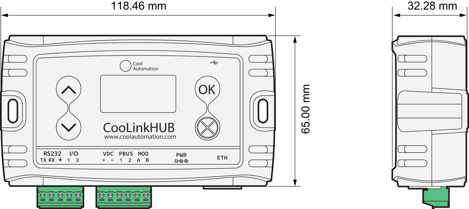
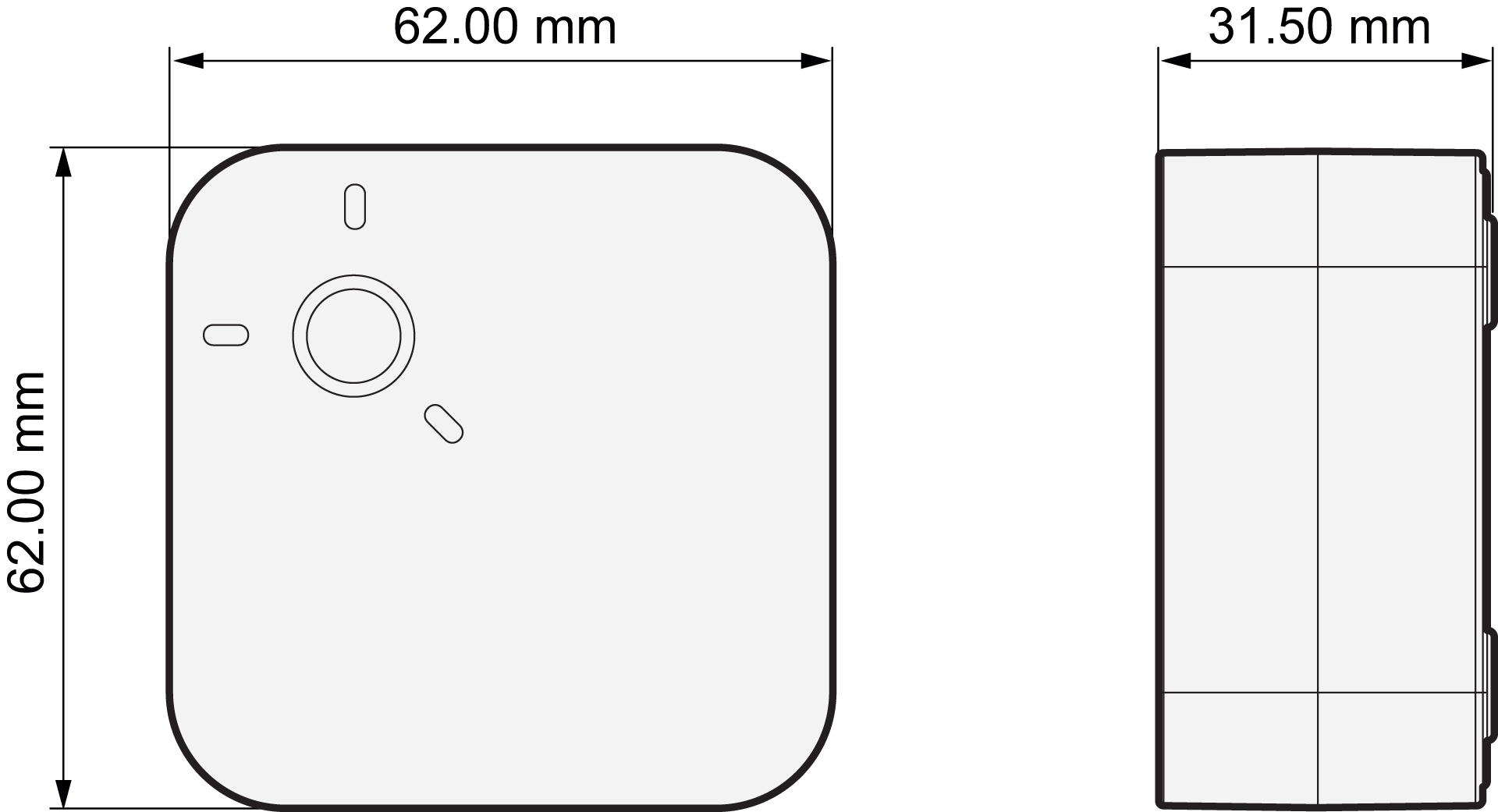
Installatie
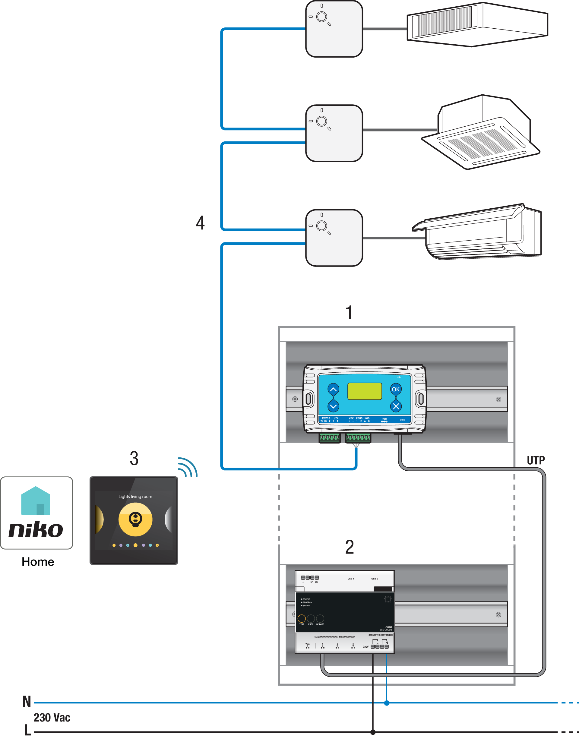
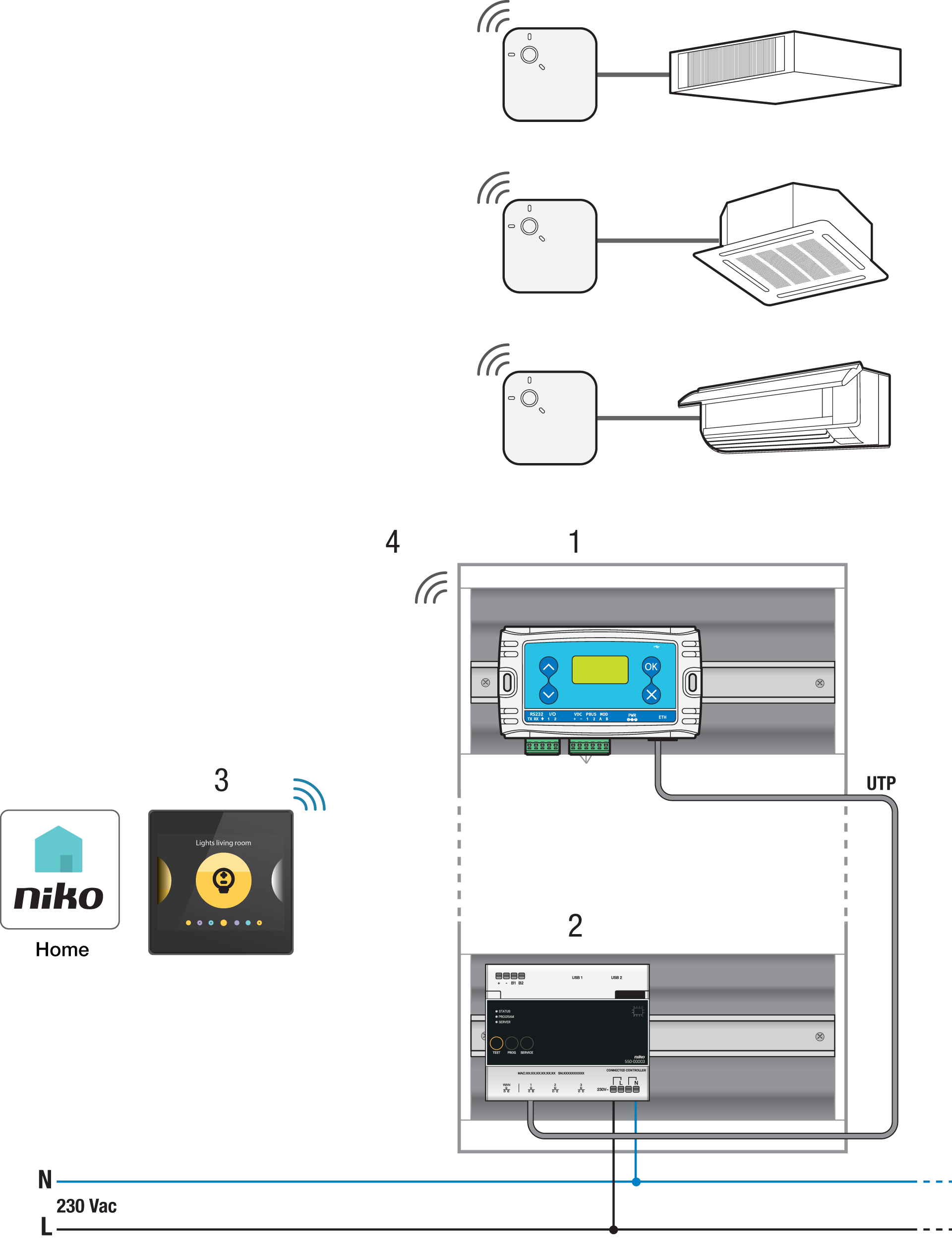
Systeemoverzicht
De CooLinkHub moet zijn aangesloten op de LAN-poort van de connected controller om communicatie met de Niko Home Control installatie mogelijk te maken.
Je kan de CooLinkHub op een van de volgende manieren op de CoolPlugs aansluiten:
bekabelde verbinding met een PBUS-kabel (2-draads, afgeschermd, twisted pair 20-24 AWG)
draadloze verbinding via een 2.4 GHz mesh netwerk
Bekabelde verbinding tussen CooLinkHub en CoolPlugs | Draadloze verbinding tussen CooLinkHub en CoolPlugs |
|---|---|
| 
|
De HVAC-interface monteren
Monteer de CooLinkHub volgens een van de volgende methodes:
Aan een muur: Gebruik schroeven om de CooLinkHub aan de muur vast te maken.
Op een metalen oppervlak/DIN-rail: Gebruik de magneten om de CooLinkHub aan de rail te bevestigen.
Monteer de CoolPlug volgens één van de volgende methodes:
Op een glad oppervlak: Gebruik de 2 dubbelzijdige klevers om de CoolPlug direct op het oppervlak te bevestigen. Je kan de draden door de zijkant van de afdekking steken.
Op een metalen oppervlak: Gebruik de 2 dubbelzijdige klevers om de magneten op de CoolPlug te bevestigen. Je kan de draden door de zijkant van de afdekking steken.
Aan een muur: Gebruik schroeven om de achterplaat aan de muur vast te maken. Je kan de draden door het gat in het midden of door de zijkant van de afdekking steken.
Op een DIN-rail: Gebruik de DIN-railachterplaat van de CoolPlug om hem op de DIN-rail te bevestigen.
Bekabelde verbinding tussen CoolPlug en CooLinkHub
Sluit de signaaldraden van de PBUS-kabel tussen de klemmen -, 1 en 2 op de CoolPlug en CDVC-, 1 en 2 op de CooLinkHub aan. Sluit meerdere CoolPlugs in serie aan (daisy chain netwerktopologie) zoals je kunt zien in Systeemoverzicht.
Draadloze verbinding tussen CoolPlug en CooLinkHub
CooLinkHubs en CoolPlugs die in dezelfde starterskit worden geleverd zijn al aan elkaar gekoppeld. Voor die CoolPlug hoef je onderstaande stappen niet te doorlopen.
Je CooLinkHub-toestel moet van stroom zijn voorzien en zijn aangesloten op de connected controller.
De CooLinkHub en CoolPlug moeten in elkaars nabijheid zijn zonder hindernissen ertussen (max. 3 meter uit elkaar).
Druk op de OK-knop op de CooLinkHub.
Kies de optie 'Wireless' met de pijltjestoetsen omhoog/omlaag.
Druk op de OK-knop.
Kies de optie 'Pair' met de pijltjestoetsen omhoog/omlaag.
Druk 5 keer op de knop op de CoolPlug. De rode led zal snel gaan knipperen.
Druk op de OK-knop op de CooLinkHub.
Als de koppeling geslaagd is:
De led op de CoolPlug stopt met knipperen.
Het aantal aangesloten CoolPlugs staat op het scherm van de CooLinkHub weergeven als L5 GXXX (XXX = het aantal CoolPlugs).
De CoolPlug aansluiten
Gebruik de HVAC-installatiehandleiding van de fabrikant om het type klemmen en hun locatie op de HVAC-binnenunit te bepalen. Kies een van de onderstaande bekabelde verbindingen:
Aansluitschema | Instructies |
|---|---|
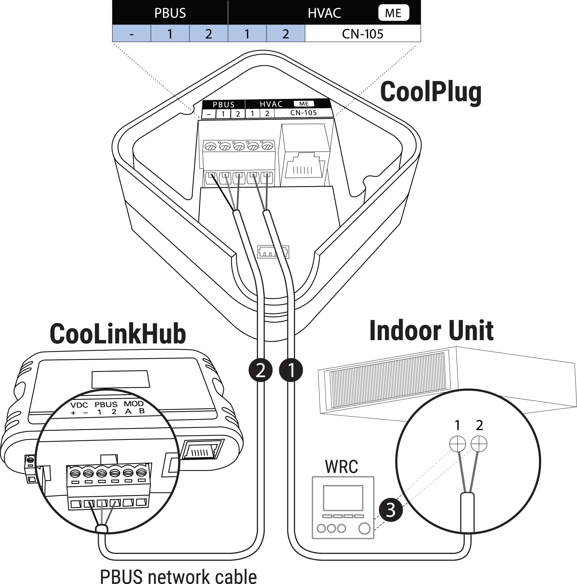 | Aansluiten op 1 en 2:
De PBUS- en HVAC-lijn hebben dezelfde klemlabels 1 en 2, maar ze behoren tot verschillende netwerken. Ze mogen niet verwisseld worden. |
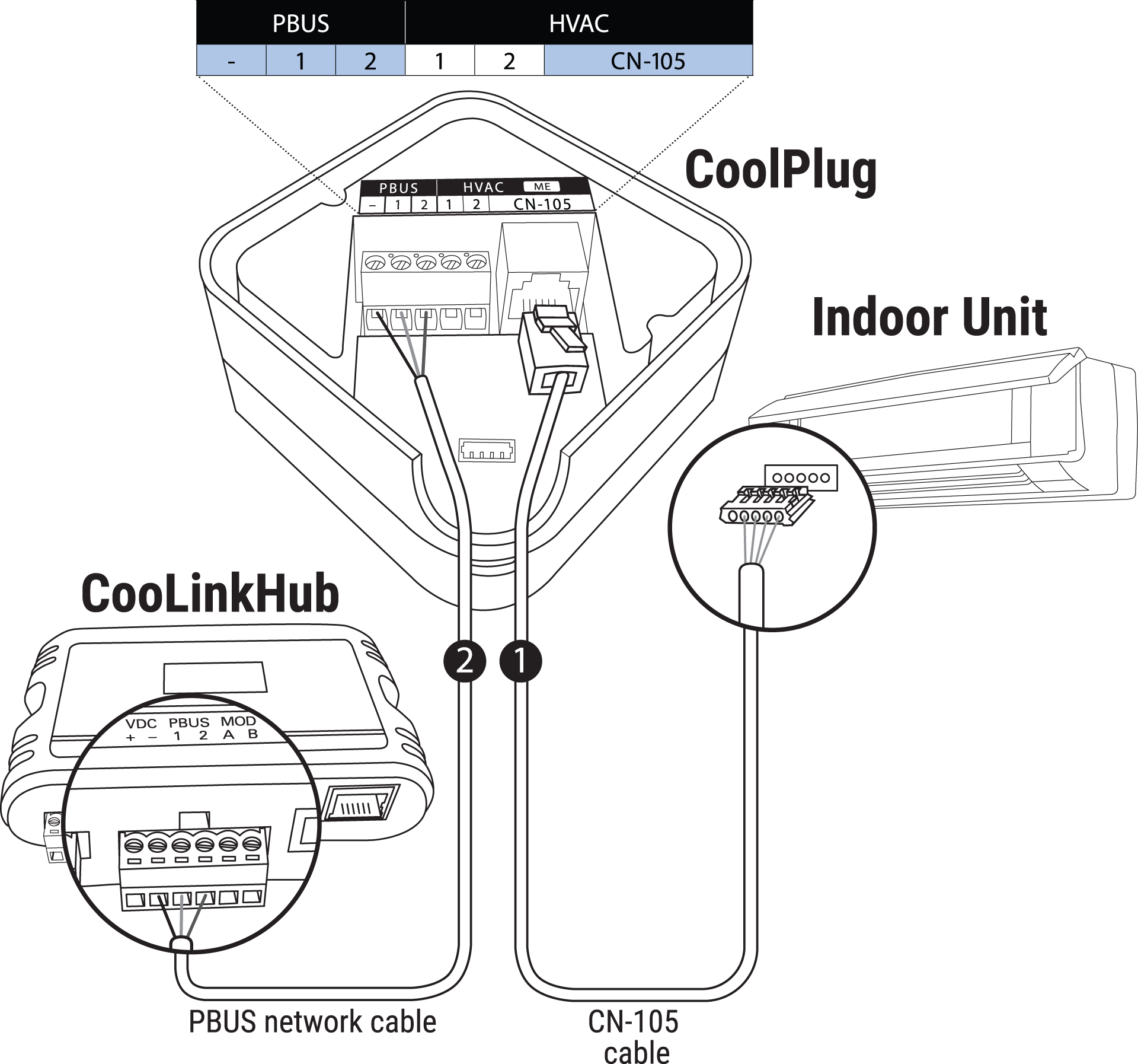 | Aansluiten op CN-105: |
Ledgedrag
Bij normale werking knippert de blauwe led af en toe en zijn de andere leds uit.
 | De blauw led knippert af en toe | HVAC is AAN |
 | Groene led brandt continu | HVAC-lijn niet aangesloten |
 | Groene led knippert | HVAC-lijn fout |
 | Rode led brandt continu | Niet gekoppeld |
 | Rode led knippert snel | Bezig met koppelen |
 | Rode led brandt en knippert af en toe | Gekoppeld, maar niet aangesloten op de CooLinkHub |
 | Amber led brandt continu | PBUS niet aangesloten |
 | Amber led knippert | PBUS fout |
Probleemoplossing
Probleem | Mogelijke oorzaak | Oplossing |
|---|---|---|
Er verschijnt geen informatie op het display | Foutieve voeding | Controleer of de 9 Vdc stroomadapter een stabiel signaal levert. |
Het aantal CoolPlugs dat op het display wordt weergegeven is niet juist. | Het HVAC-systeem herkennen duurt enkele minuten. De communicatie met het HVAC-systeem verloopt niet correct. |
|
Foutcodes
Code | Foutbeschrijving |
|---|---|
CP01 | CoolPlug heeft geen verbinding met de HVAC-eenheid |
CP02 | Geen communicatie met het CoolPlug-toestel |
CP03 | CoolPlug-toestel is in BOOT-modus |
CP04 | CoolPlug is niet goed geconfigureerd |
CP05 | CoolPlug kan de HVAC-eenheid niet detecteren |
Resetprocedure
Je kan de CoolPlug resetten om de instellingen voor de draadloze verbinding te verwijderen.
Druk één keer kort en dan één keer lang op de CoolPlug.
