Use case
Your customer has a combined heating system with 7 zones. Five zones are equipped with a zone valve controlled by a thermostat. Two zones are equipped with electrical heating controlled by a thermostat. A circuit pump is optional.
You can also use push buttons with LED(s) and comfort sensors instead of thermostats, or a combination of both.
Procedure
Creating the controls and the devices
-
Create the thermostats (THT1 to THT7).
-
Create the zone valves (VALVE1 to VALVE5).
-
Create a heating system (H/C1).
-
Create the electrical heatings (HEAT1 and HEAT2)
-
(optional) Create a circuit pump (PUMP1).

When there is no circuit pump in the installation, there is no need to configure it in the software.
Creating the routines
-
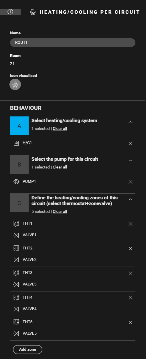
Create a routine Heating/cooling per circuit (ROUT1). Use the following behaviour:
-
Select the heating system (H/C1).
-
(optional) Select the circuit pump (PUMP1).
-
Define the heating zones. Combine the correct thermostat with the corresponding zone valve (THT1 and VALVE1, THT2 and VALVE2, ..., THT5 and VALVE5).
-
(optional) Create notifications.
-
-
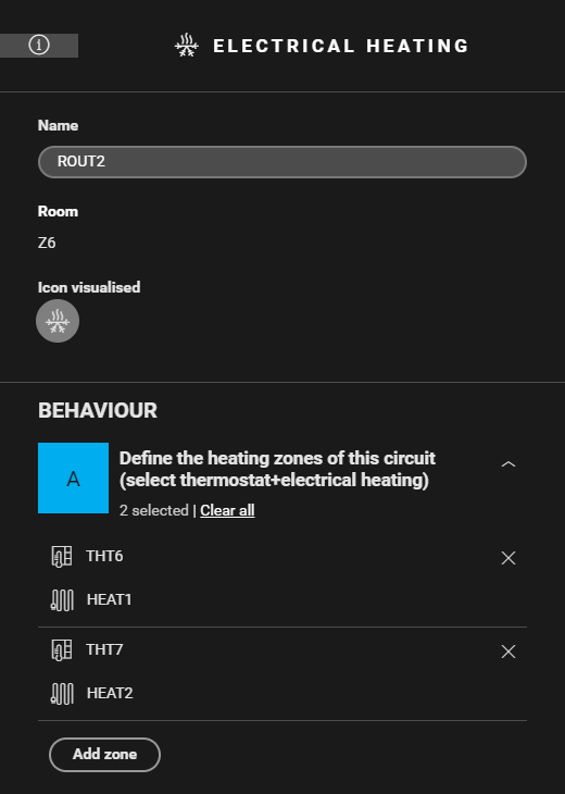
Create a routine Electrical heating (ROUT2). Use the following behaviour, select the electrical heating and corresponding thermostat per zone (HEAT1 and THT6, HEAT2 and THT7).

Filling the cabinet and addressing the devices
-
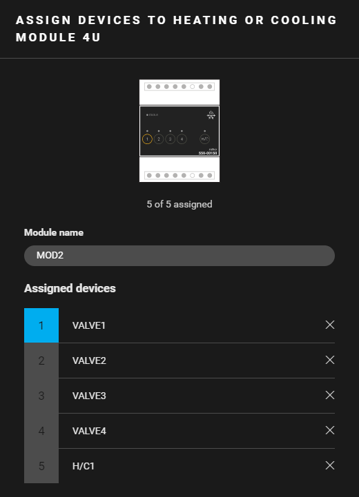
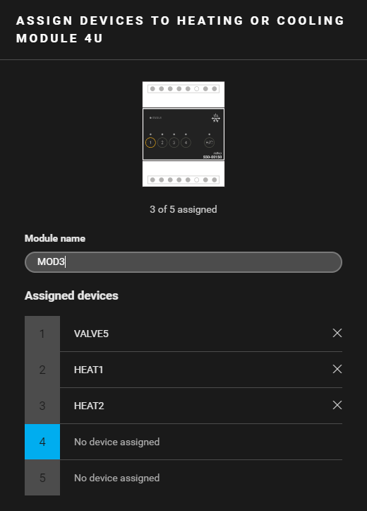
You can only address four zone valves to a heating or cooling module 4U. Contact 5 of the module is an H/C-contact.
-
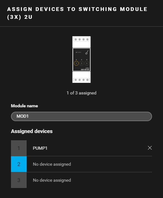
Always address the heating system to the first heating or cooling module in the cabinet (contact 5).
|
Fill the cabinet with ... |
and address the following devices ... |
|---|---|
|
a switching module (3x) 2U (MOD1) |
the circuit pump PUMP1 (*). |
|
a heating or cooling module 4U (MOD2) |
|
|
a heating or cooling module 4U (MOD3) |
|
(*) You can also address the circuit pump to the H/C contact of another heating or cooling module.
(**) This contact is not physically used in the installation.
(***) The contact closes when one of the thermostats demands heating.
Example
Click here to download the programming example (nhc2 file).
Connection diagram
The figure below shows a connection diagram. In this example, radiators, but also underfloor heating and electrical heating, are used.
