Use case
Your customer has a heating and cooling system with 5 zones combined with a heat pump. Each zone is equipped with a zone valve controlled by a thermostat.
The heat pump controls whether the house is cooled or heated, via the thermostats.
The thermostats can be switched from "cooling" to "Prog 1".
You can also use push buttons with LED(s) and comfort sensors instead of thermostats, or a combination of both.
Procedure
Creating the controls and the devices
-
Create the thermostats (THT1 to THT5).
-
Create a digital sensor (SENS1).
-
Create the zone valves (VALVE1 to VALVE5).
-
Create a heating/cooling system (H/C1 and H/C2).
-
(optional) Create a circuit pump (PUMP1).

When there is no circuit pump in the installation, there is no need to configure it in the software.
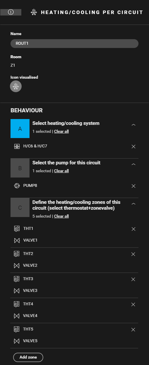
Creating the routine
Create a routine Heating/cooling per circuit (ROUT1). Use the following behaviour:
-
Select the heating/cooling system (H/C1 and H/C2).
-
(optional) Select the circuit pump (PUMP1).
-
Define the heating/cooling zones. Combine the correct thermostat with the corresponding zone valve (THT1 and VALVE1, THT2 and VALVE2, ...).
-
(optional) Create notifications.
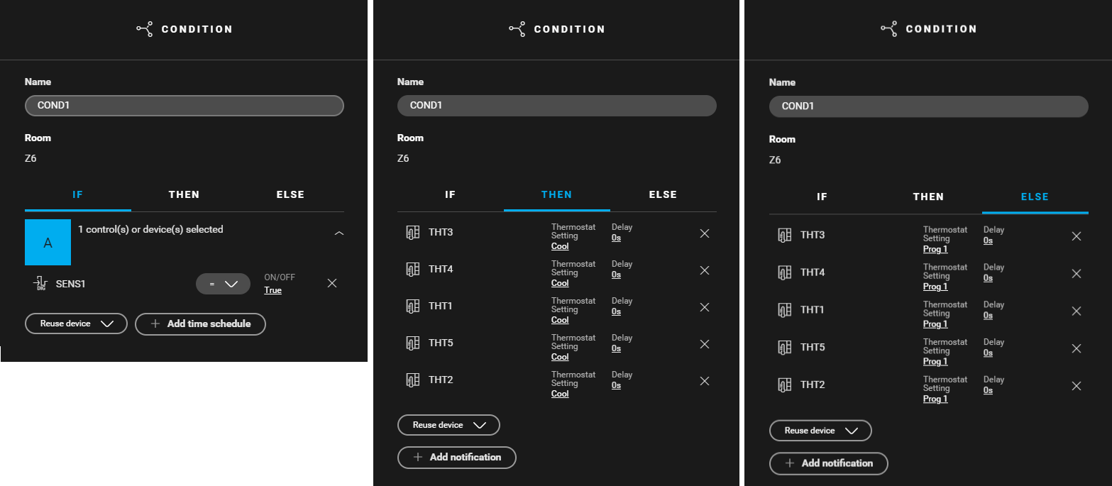
Creating the condition
Create a condition (COND1) for the heat pump (digital sensor) to control the thermostats. Use the following logic:
-
IF SENS1 = true
-
THEN THT1 to THT5: Thermostat setting = COOL
-
ELSE THT1 tot THT5: Thermostat setting = Prog 1

Filling the cabinet and addressing the devices
-
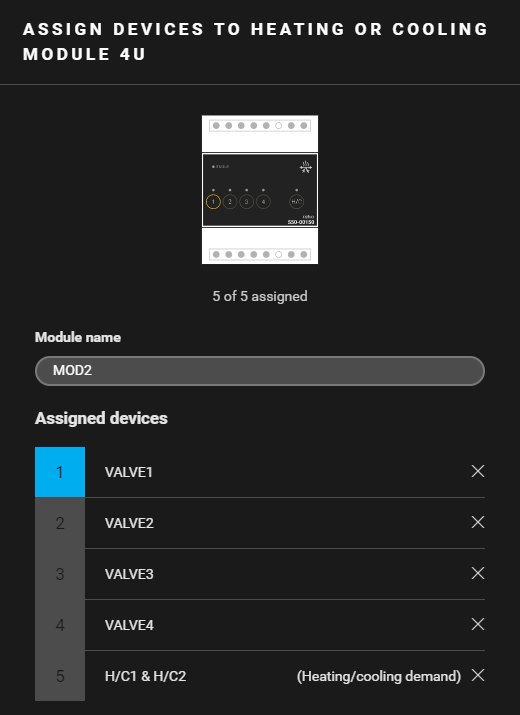
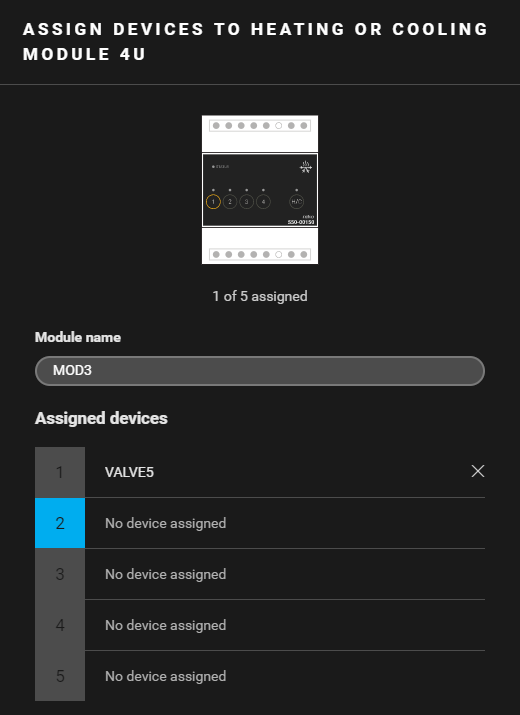
You can only address four zone valves to a heating or cooling module 4U. Contact 5 of the module is an H/C-contact.
-
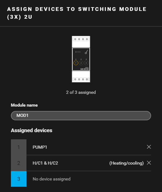
Always address the heating/cooling system to the first heating or cooling module in the cabinet (contact 5).
|
Fill the cabinet with ... |
and address the following devices ... |
|---|---|
|
a switching module (3x) 2U (MOD1) |
|
|
a heating or cooling module 4U (MOD2) |
|
|
a heating or cooling module 4U (MOD3) |
the zone valve VALVE5. |
|
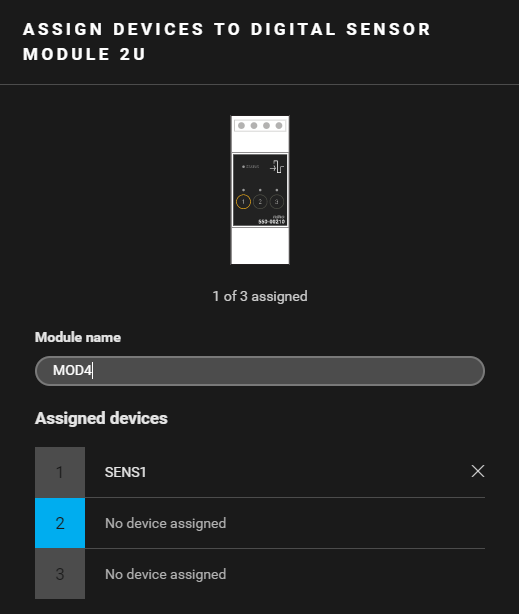
a digital sensor module (MOD4) |
the digital sensor SENS1. |


(*) This contact is not physically used in the installation.
(**) This contact is used for switching the heat pump from cooling to heating.
(***) The contact closes when one of the thermostats demands heating or cooling.
Example
Click here to download the programming example (nhc2 file).