Description
The pulse counter allows you to monitor gas, water and electricity consumption as well as electricity production.
Overview
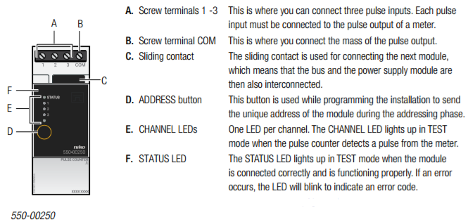
This module has three pulse inputs. It can therefore connected to up to three metres. The pulse counter counts the pulses and converts the sum into m³ or kWh.
The scale factor of the pulses (e.g. 1 pulse = 10 litres) and the meter type (gas, water or electricity) can be selected via the programming software.
The eco-display shows the total electricity consumption and the electricity production, if applicable. A detailed overview of the history of the energy consumption can be requested via the touchscreen*, a smartphone* or the Niko Home Control energy software.
The pulse counter should not be used for billing purposes. Only the data recorded by the meter of the energy supplier are valid for billing purposes. The data recorded by the pulse counter should be used for information purposes only.
Selecting the correct measuring module
There are a few options available for measuring electrical data. Based on the number and type of channels you wish to measure, you can either select an electricity measuring module with one channel, an electricity measuring module
with three channels, or a pulse counter for three channels in conjunction with a meter with pulse output. See Electricity measuring modules.
A maximum of 20 channels can be measured per installation.
The measuring data is then stored in the memory of the connected controller (light). This data can be exported, backed up and restored using the Niko Home Control user settings software (consult the Niko Home Control manual). How long the
* Not possible with the light version of the connected controller.
connected controller (light) will store this data for will depend on the number of channels in the installation. An overview is provided in the table below. If the resident wishes to store this data for an extended period of time, then he or she must export this data using the Niko Home Control user settings software before the existing data will be overwritten.
|
Number of channels |
Storage capacity of the connected controller (light) |
|
3 |
9 years |
|
9 |
3 years |
|
15 |
1.5 years |
|
20 |
1 year |
Installation
Wiring diagram
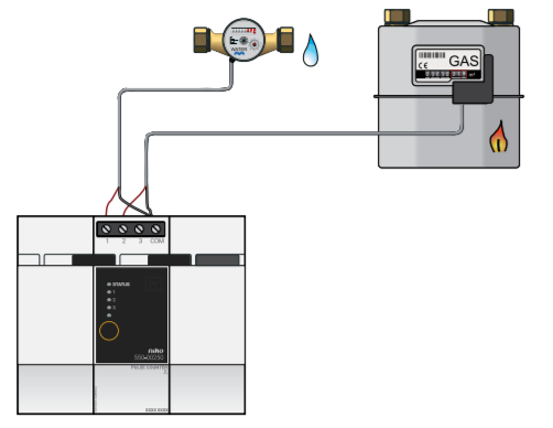
Fitting a meter with pulse output
There are three options for fitting a meter with pulse output:
-
An add-on device is available from the wholesaler’s for most gas meters supplied by the energy supplier. This device clips onto the meter housing and generates a pulse whenever a certain amount of gas has been used. In a lot of cases, this add-on device can also be used on existing meters. Contact the gas meter manufacturer for more information.
-
For a newly constructed dwelling, you can ask the client (building supervisor or architect) to request a gas or water meter with pulse output from the energy supplier.
-
You can ask the installer of the heating or sanitary system to install a separate gas or water meter with pulse output.
Connecting and mounting the gateway
Follow the steps below to mount and connect the pulse counter:
-
Ensure that the installation is disconnected from the mains.
-
The cable distance between the module and the pulse output should not exceed 50 m.
-
A maximum of three meters can be connected to each module.
-
If you establish a connection with the gas meter, make sure that the pulse output is galvanically isolated from the meter housing. In most cases, an add-on meter interface that generates pulses via an internal magnetic contact switch (reed contact) can be clipped onto the meter.
1 Press the module onto the DIN rail until it clicks into place. Preferably position the pulse counter in the top row inside the electrical cabinet to keep the SELV cables separate from the 230V cables.
2 Connect the pulse outputs to screw terminals 1-3.
3 Connect the mass of the pulse outputs to the common screw terminal COM.
4 Connect the module to the module before it. Slide the sliding contact of this module to the right until it clicks into the pulse counter. This will ensure that the bus and the power supply voltage are connected.
Programming the pulse counter
Use the programming software to select the currency of your choice: EUR, GBP or SEK. Gas and water consumption are expressed in m³, and electricity in kWh. The following settings can be selected per channel:
-
channel name.
-
channel type: gas, water, electricity.
-
pulse conversion factor:
-
1 - 1,000 pulses/m³ for gas and water.
-
1 - 10,000 pulses/kWh for electricity.
-
for electricity: global, consumer, amount generated.
-
-
If the voltage at the power supply of the Niko Home Control installation is disrupted, no data will be logged, even if electricity is still being consumed or produced by the switching circuits measured.
-
You will lose all data of a channel if you use the programming software to:
-
remove the channel.
-
change the energy type (electricity/gas/water).
-
change the measurement type.
-
Error codes
When the module is functioning properly, the STATUS LED will light up in TEST mode only. If one or several errors occur, the LED will blink to indicate the error code of the error with the highest priority. The table below provides an overview of all error codes.
|
LED |
ACTION |
ERROR |
POSSIBLE CAUSES |
|
STATUS LED |
Blinks – one pulse per two seconds. |
Communication error |
The module is faulty or nothing has been connected to the connection terminals. |
Technical data
-
-
maximum pulse frequency per input: 10 Hz
-
minimum pulse duration: 30 ms
-
only for meters with a pulse output isolated from the mains in accordance with SELV requirements (safety extra-low voltage)
-
4 screw terminals for 3 x 1.5 mm² or 2 x 2.5 mm² or 1 x 4 mm²
-
sliding contact to connect the module to the following module on the DIN rail
-
dimensions: DIN 2U
-
CE marked
-
ambient temperature: 0 - 45 °C
-