
The installation should be carried out by a qualified installer and in accordance with the regulations of the local distribution system operator.
Step 1
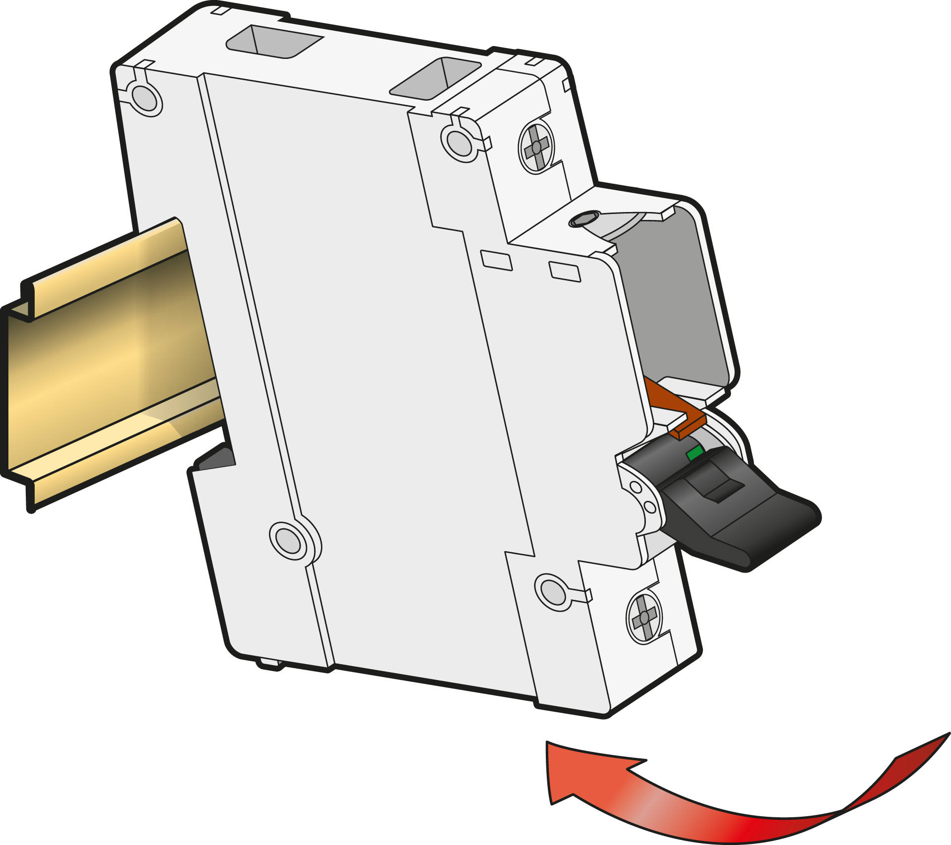
Click onto the DIN rail, according to IEC/EN 60715.
-
TYTAN® I must always be mounted horizontally.
-
Pay attention to the rated diversity factor (RDF) according to IEC/EN 61439-1.
-
It is recommended to mount a cassette with fuse plugs (961-9210300) on the DIN rail next to the fuse(s), to make spare fuse plugs readily available. Replacing a blown fuse plug with a spare one avoids touching the hot fuse.
Step 2
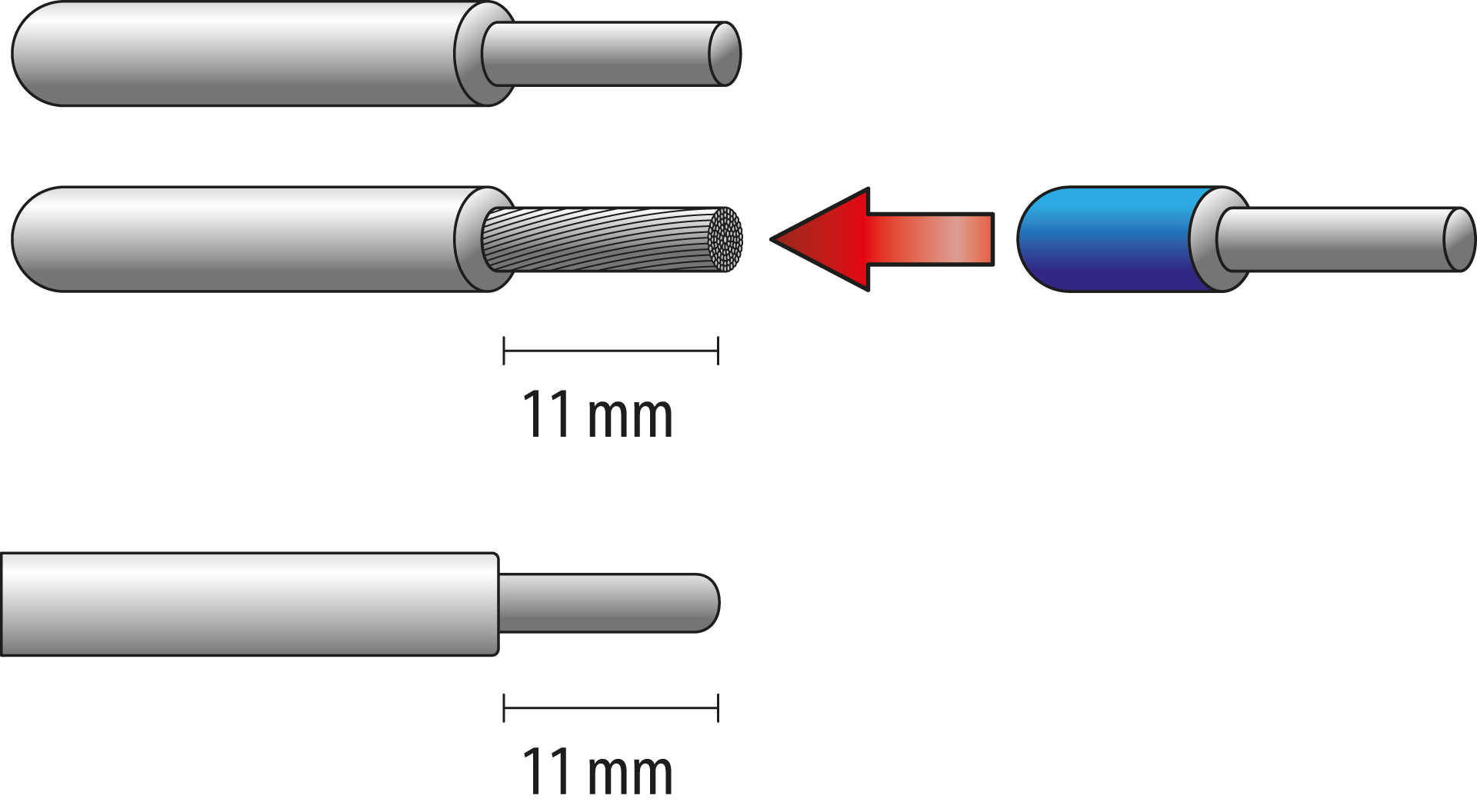
Only use suitable wires:
-
Copper
-
Rigid, stranded or flexible
-
Cross section 1,5 – 25 mm2 (max. 2 x 10 mm2)
Strip the wires. Use ferrules for flexible wires.
Step 3
Feed the main wires at the bottom of the fuse switch disconnector and the consumption at the opposite side. Secure with 3 Nm, using a PZ2 screwdriver.
Use the wiring diagram to connect the wires correctly.For the maximum number of wires that can be connected, refer to the table below.
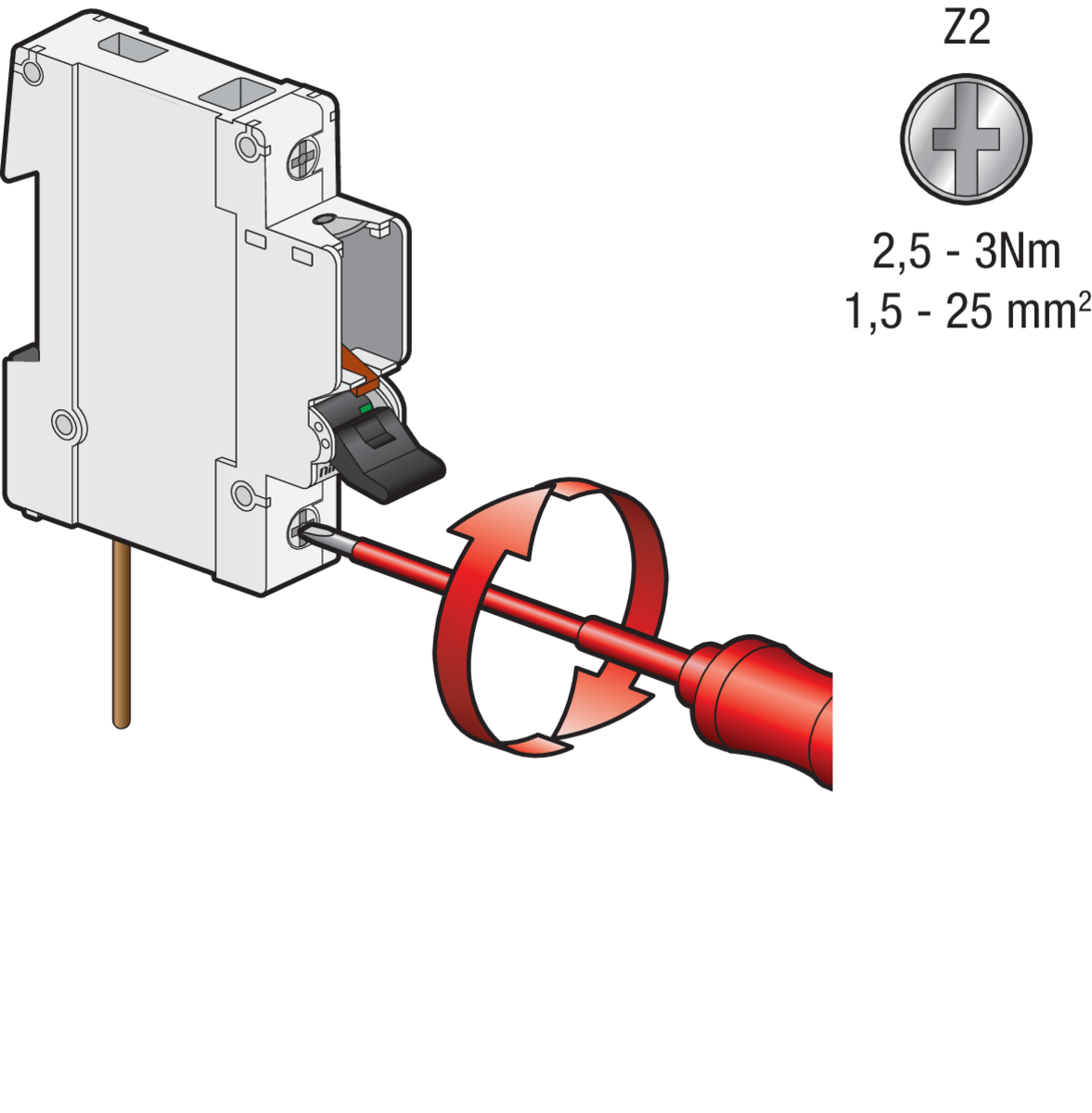
Make sure to correctly connect the fuses. The load side is the side where the fuses are connected to the installation. The feed side is the side where the power is connected. Reversing the connection poses a an electrocution risk. Always feed at the bottom.
Maximum number of wires
|
Max number of wires |
Wire cross section |
|---|---|
|
4 |
1.5 mm2 |
|
4 |
2.5 mm2 |
|
4 |
4 mm2 |
|
3 |
6 mm2 |
|
2 |
10 mm2 |
|
1 |
16 mm2 |
|
1 |
25 mm2 |
Step 4
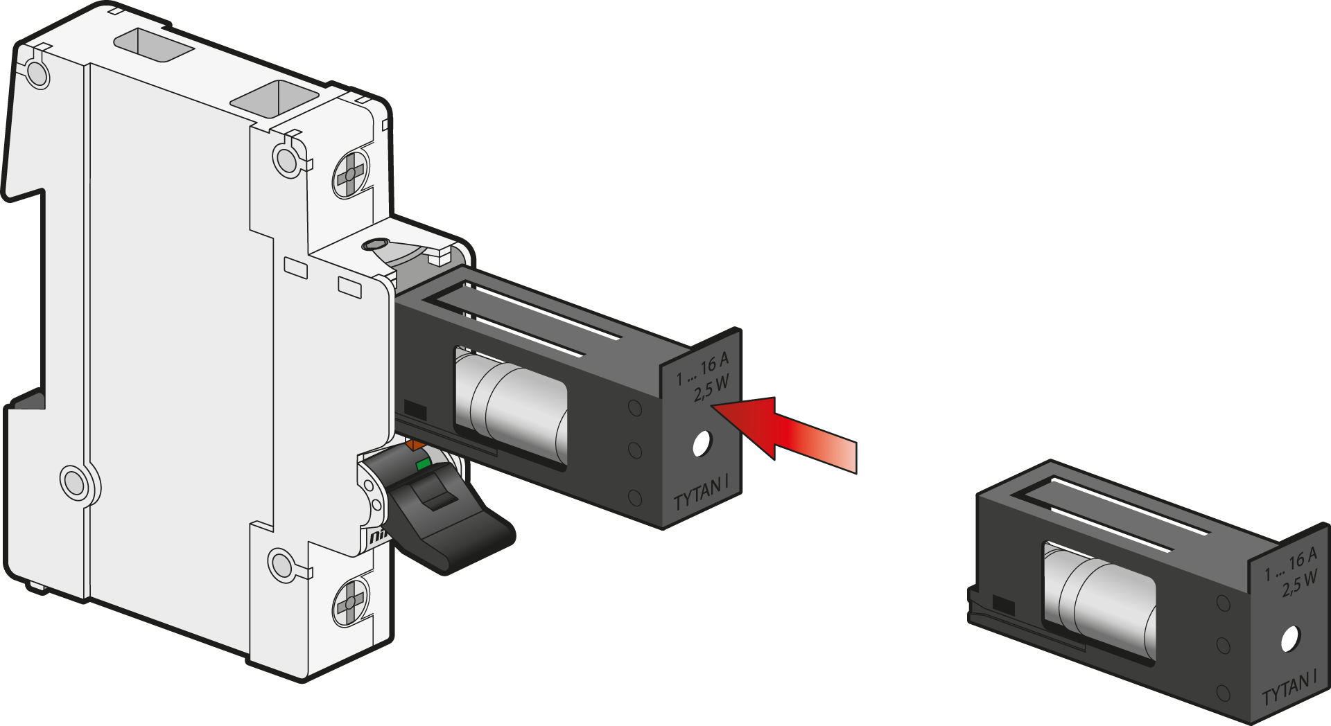
Insert the fuse link in the fuse-plug (961-9210300).
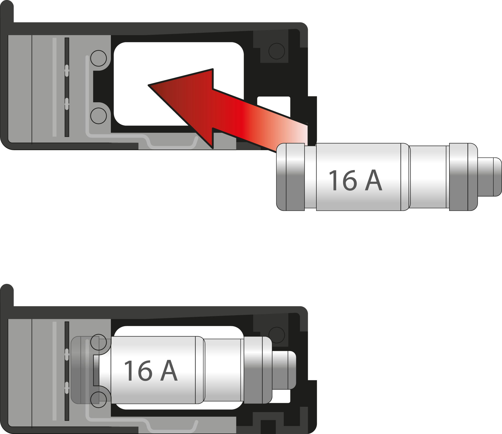
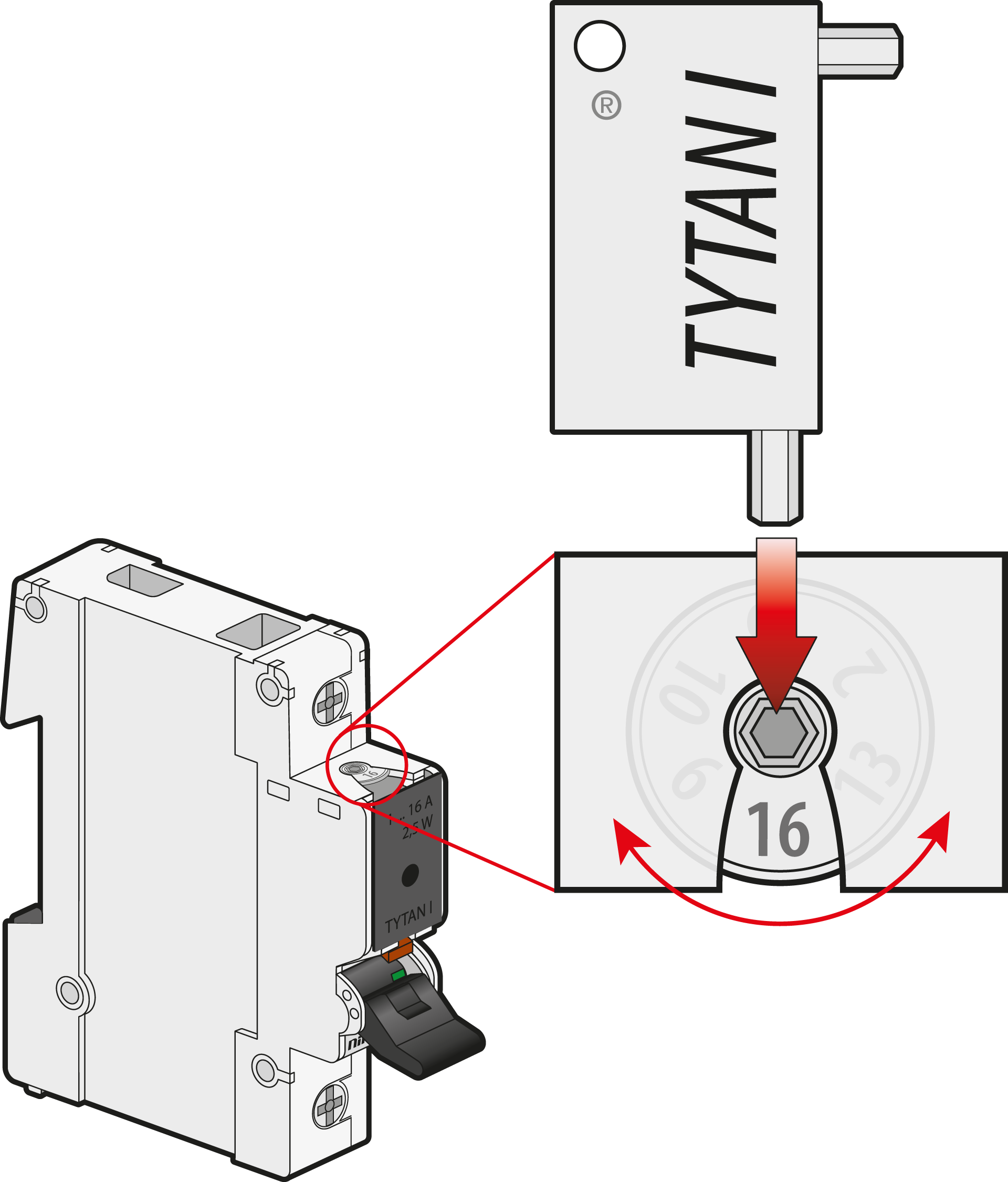
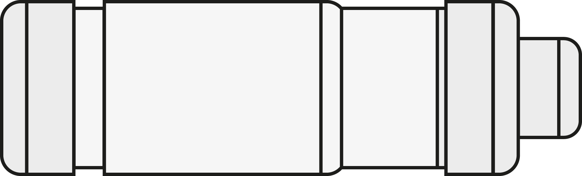
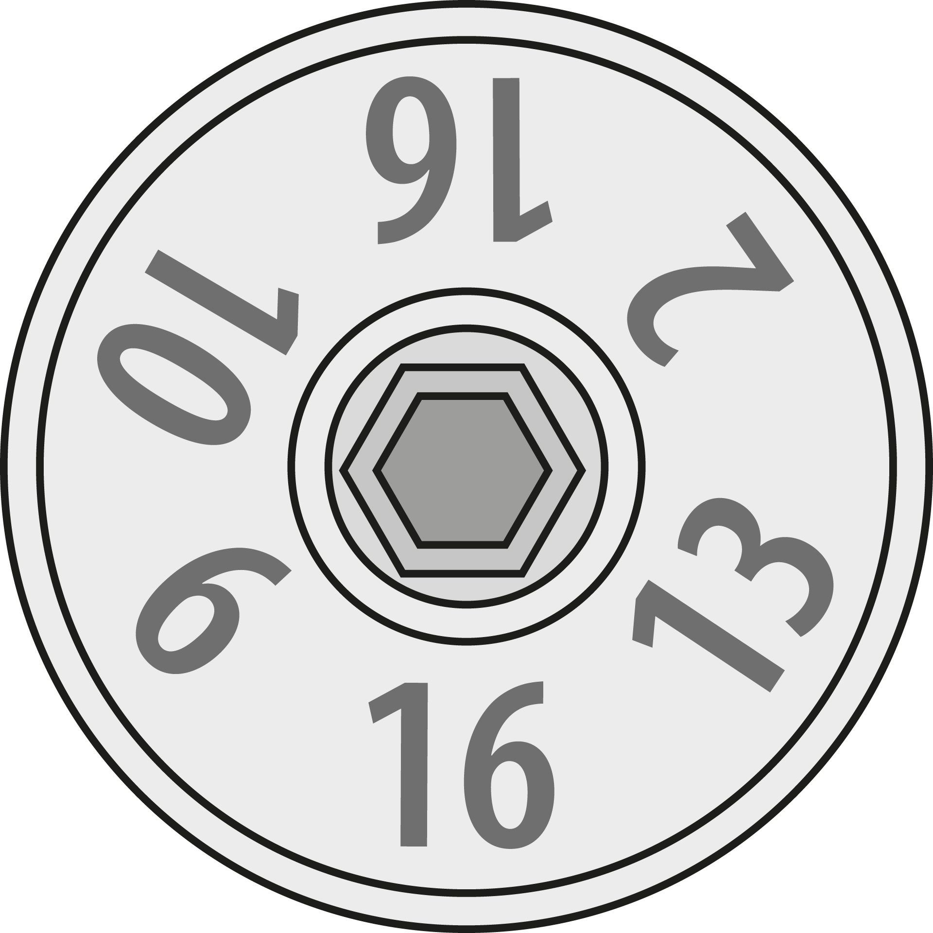
Set the correct value according to the fuse link that is used:
|
|
2 A |
4 A |
6 A |
10 A |
13 A |
16 A |
|

|

|

|

|

|

|
|
2 |
4 |
6 |
10 |
13 |
16 |
Step 5
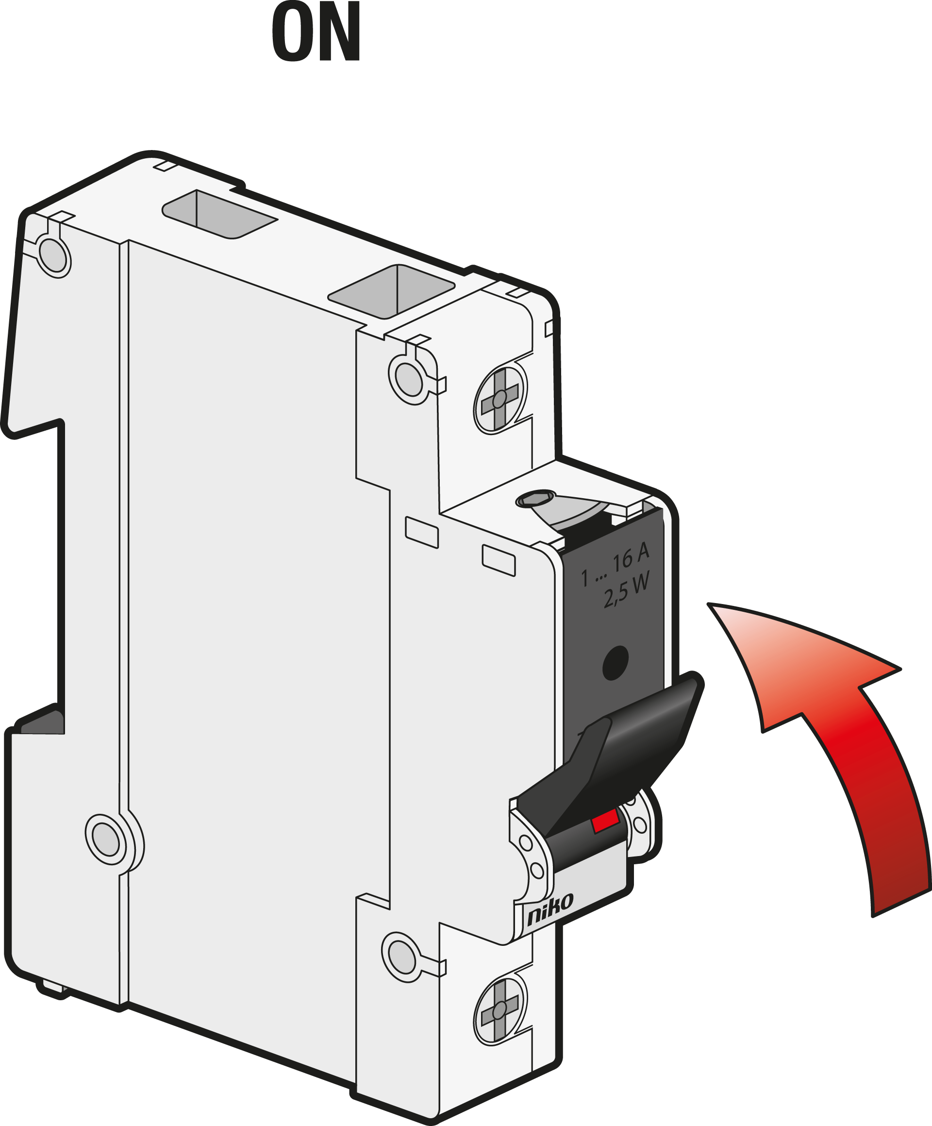
Switch ON.
Step 6
Check the fuse within 24 hours after switching ON:
-
The average operation temperature must be less or equal to 35 °C.
-
The terminals must remain secured at 3 Nm.