What do you need?
Niko requirements
Your Niko Home Control installation meets the following requirements:
-
It has a connected controller II.
-
It is configured with the most recent programming software.
Depending on the type of contacts on your ventilation system, you need one of the following additional products for each ventilation zone:
If you are using wireless interaction devices for your ventilation system (e.g., buttons), the wireless bridge is strictly necessary.
Vasco requirements
Your system meets the following requirements:
-
It is a ventilation system C or D.
-
Your ventilation device can be controlled in at least one of the following ways:
-
Via two or three contacts to set different speeds
-
Via one 0 – 10 V contact
-
-
It is compatible with the Niko module (see Niko requirements).
Your system is one of the following Vasco products*:
The table shows the relevant contacts that are present on each product. If a type of contact is not present, it is shown as “-”.
|
|
Two or three contacts to set different speeds |
One 0 – 10 V contact |
|---|---|---|
|
225 Compact Type D |
X9 (L1, L2, L3) |
X26
|
|
DX4-DX5-DX6 |
||
|
D350-D425 |
||
|
D275 |
||
|
C400 RF |
L1, L2, L3 |
- |
*Consult the website of the supplier for detailed specifications and the latest products.
Wiring diagrams
Consult the manufacturer’s manual for the full installation procedure and the necessary settings.
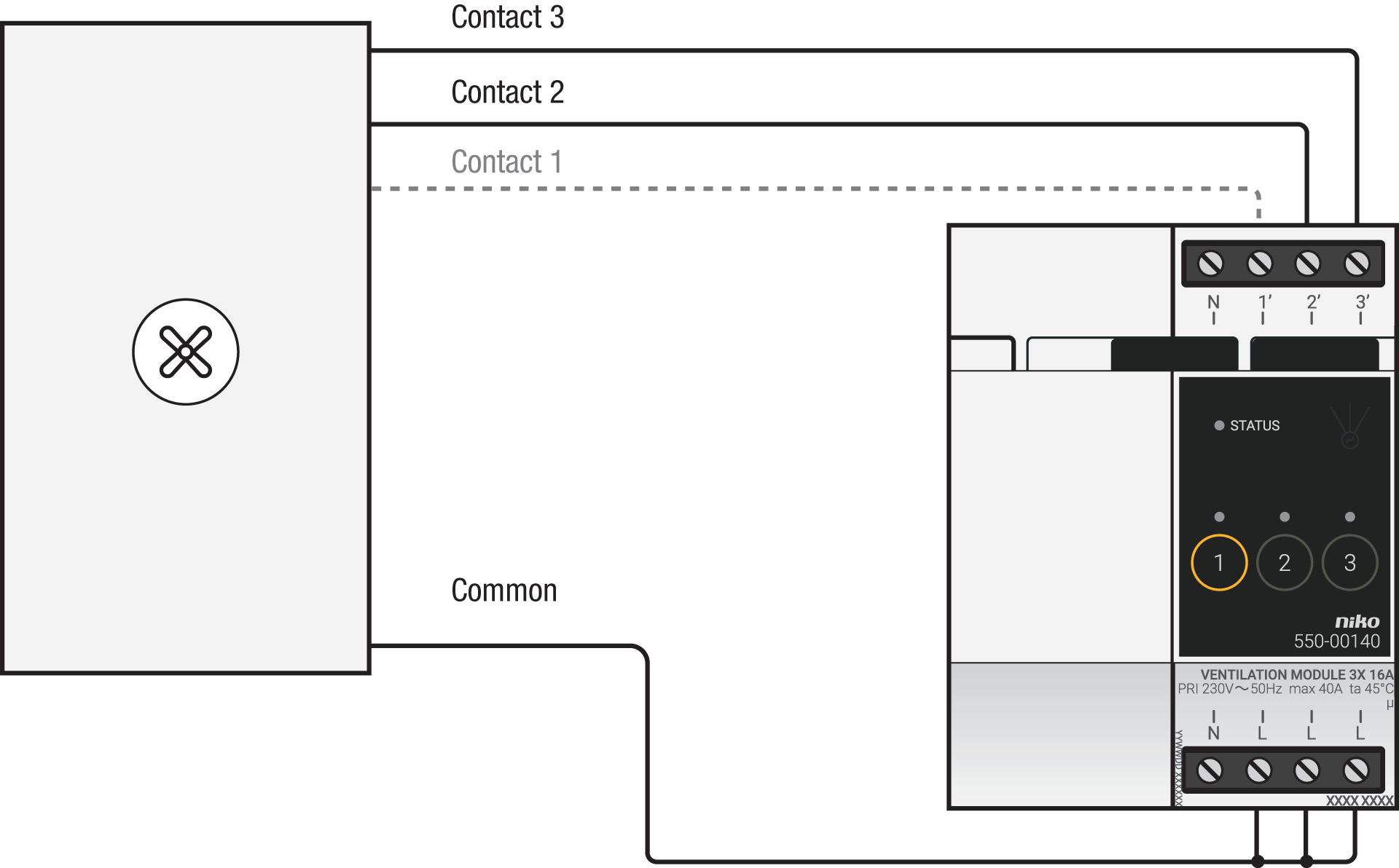
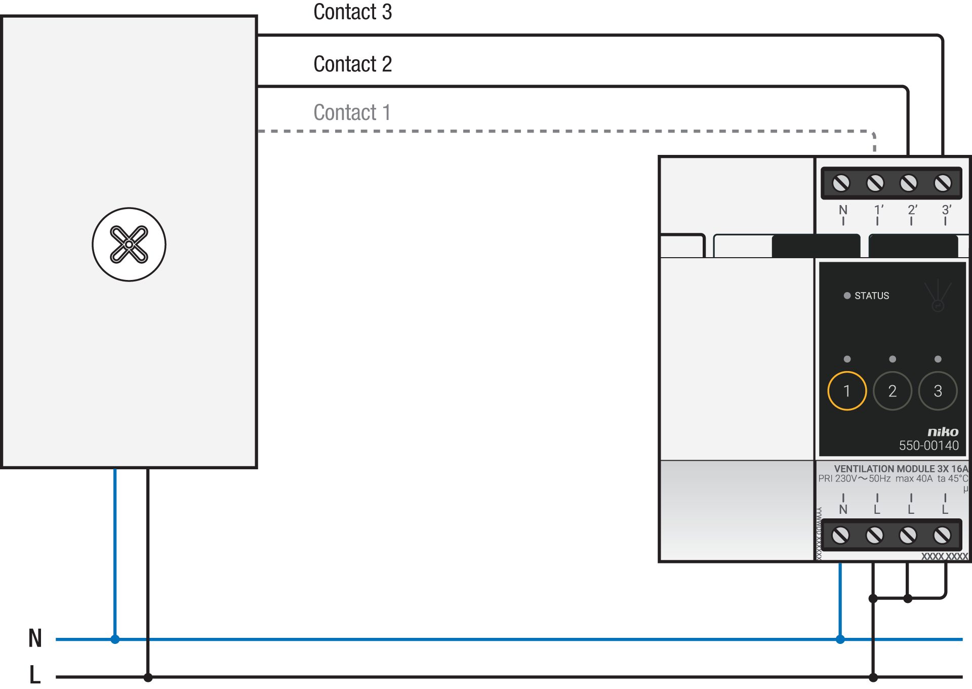
Connecting the ventilation module
|
Via potential-free contacts |
Via 230 V contacts |
|---|---|
|
|
Connect two or three wires, depending on the available contacts on your ventilation system:
|
Ventilation setting |
Three-wire |
Two-wire |
|---|---|---|
|
low |
contact 1 |
* |
|
normal |
contact 2 |
contact 2 |
|
high |
contact 3 |
contact 3 |
*With a two-wire control, you connect the common (from the ventilation unit) in between two control wires. If no control wire is selected, the ventilation system will function at the lowest setting.
Connecting the analogue control module
Connect contact 1 on the Niko analogue control module to the 0 – 10 V contact on the ventilation system, as shown in the wiring diagram.

Programming
Configure the ventilation module or analogue control module via the Niko Home Control programming software. For more information, see https://guide.niko.eu/en/smnhc2/lv/creating-a-control-or-a-device
You need to set the boost time. In the case of an analogue control module, you also have to define the voltage for the three fan speeds.