Description
The connected controller is the central module of every Niko Home Control installation. It covers all basic functions on which a Niko Home Control installation is built. The basic functions include:
- The intelligence directing the Niko Home Control installation. Through the programming software, the logic is saved locally on the controller.
- The power supply module providing an input voltage of 26 Vdc to the bus, the cabinet modules and the controls. Depending on the size of the installation, separate power supply modules can be added. For more information on the required number of power supplies, see Additional power supply unit.
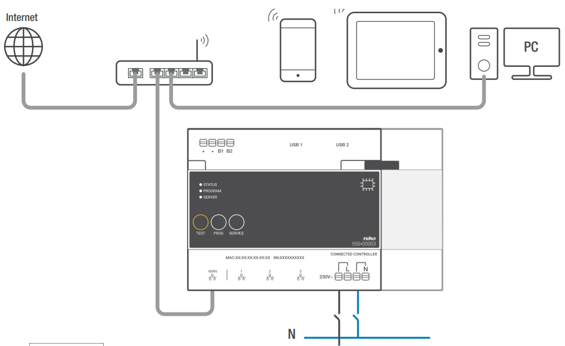
- The connection to Niko Home Control IP devices such as touchscreens and/or external video units. A built-in router allows the user to connect up to three devices directly to the controller. With an extra switch, this number can be increased.
- The connection to the home network and the internet. This enables the user to control the installation both indoors and outdoors (via mobile networks such as 3G, 4G, GPRS or a Wi-Fi hotspot) using mobile devices (smartphones and tablets with iOS or Android). It also ensures that you can use the Niko Home Control User settings software on PC/Mac and on the eponymous app on mobile devices.
Overview

Operation
The module includes a TEST button to verify the proper functioning and status of all other modules.
After registering on the registration page https://mynikohomecontrol.niko.eu you can control your installation with your smartphone or tablet (via mobile networks like 3G, 4G, GPRS or a Wi-Fi hotspot) and enjoy the Niko Upgrade or Diagnostics services of the installation.
Installation
Wiring diagram
Mounting instructions
Each installation must consist of one connected controller. Follow the steps below to mount the connected controller:
- Ensure that the installation is disconnected from the mains.
- This product must be secured with a miniature circuit breaker of max. 6 A in the electrical cabinet.
- Click the controller onto the DIN rail, ideally at the bottom left in the Niko Home Control part of the electrical cabinet.
- Now mount the other modules onto the rail, from left to right. Do not place any dimming modules immediately next to, above or below the controller. When there is no room left on the rail or the maximum number of 12 devices per rail has been reached, you simply continue on the rail above. Each following rail must start at the left with a rail coupler or an extra power supply if required (see Additional power supply unit).
- Connect the connected controller with the module, placed next to it by sliding the sliding contact of the controller to the right until it clicks. This will ensure that the bus and the power supply voltage are connected.
- Connect the network cable to the WAN gateway of the connected controller and connect it with the internet modem or router of the resident. Use a shielded network cable, preferably a STP network cable, and keep it separate from 230 V cables to avoid crosstalk. Run the network cable alongside the SELV cables, for instance. The resident must ensure that the network is secure.
- Connect the Niko Home Control IP devices of the installation such as the touchscreens and/or external video units to the other three ports. If you have to connect more than three IP devices, you can use an Ethernet switch (no router!).
- Connect the L phase wire and the N neutral wire to the L and N screw terminals respectively and switch on the mains supply.
Remember to give the resident the information listed on the sticker or to place the sticker in a clearly visible location on the connected controller or inside the electrical cabinet. The sticker includes the MAC address and serial number (SN) of the connected controller. The resident needs this information to register via https://mynikohomecontrol.niko.eu.
Power supply dimensioning
Depending on the size and the structure of the installation, up to two extra power supplies are installed next to the built-in power supply in the connected controller. As a rule of thumb to determine if you need additional power, you can use the following quick check: The power supply built into the controller can be up to 24 cabinet modules and 70 controls (of which 20 with indication LED). For larger installations, consult the point calculation, see Additional power supply unit. Each control and module consumes a specific amount of energy. This consumption is expressed in points. An additional power supply is necessary as of 800 points.
Check the status of the installation
Using the indication LEDs on the controller
If the Niko Home Control installation functions normally, only the SERVER LED is illuminated on the connected controller. The remaining LEDs are not lit, to help save energy.
If an error occurs, simply switch the installation to TEST mode to check the status of the modules. First press the TEST button on the controller to switch the installation to TEST mode. The STATUS LEDS indicate the status of each module and each output. The TEST mode remains active for eight hours.
On the controller are three LEDS providing more information on the controller and the installation:
LED | Status | Information | Possible causes and actions |
STATUS LED | The green LED lights up continuously | The installation functions normally. | / |
The green LED flashes | The installation is initializing or is currently being updated. | After approximately one minute, the status ends automatically. Under no circumstances should the installation be switched off. | |
The orange LED lights up continuously | A problem has been detected. | Consult the diagnostics page in the programming software for more information (see Using the diagnostics page). | |
The red LED lights up continuously | A serious problem has been detected. | Consult the diagnostics page in the programming software for more information (see Using the diagnostics page on page). | |
The LED is not on | The controller does not receive power supply voltage or is defective. | Check if the TEST mode is active. Measure the power supply voltage. If the problem persists, contact the Niko customer service. | |
PROGRAM LED | The green LED lights up continuously | The controller is in manual program mode | In an installation programmed with programming software 2.0, this LED has no function |
SERVER LED | The green LED lights up continuously | The connection with the Niko server is working properly and the installation was registered correctly. | / |
The orange LED lights up continuously | The connection with the Niko server is working properly but the installation was not yet registered. | Use the information of the controller (MAC address and serial number SN found on the controller and the included label) to register the installation on https://mynikohomecontrol.niko.eu. | |
The red LED lights up continuously | No communication possible with the Niko server. The internet connection was interrupted or the Niko server is not accessible. | Please check the internet connection. If the internet connection is working properly, contact the Niko customer service. |
Using the diagnostics page
The advantage of installations with a connected controller is that they can be monitored in detail with the diagnostics page. You can consult it via the programming software.
The diagnostics page is a valuable tool for the installer to detect errors. After all, it allows to quickly analyse the proper functioning and the set-up of the installation. For example, you can monitor the bus communication live and check which controls and/or modules have not yet been programmed on the bus.
Programming the installation
Program the installation with the most recent version of the programming software (available on www.niko.eu) and load it to the connected controller. If you add additional modules to the installation, you will need to reprogram the installation in order for the modules to work.
Follow the steps below to program the installation:
- Connect the installation to the mains power supply.
- Press the TEST button and verify that the STATUS LED of each module lights up. This way you are certain that all sliding controls between the modules were closed properly.
Connect the computer to the installation:
- If a router is already present for the home network, you can:
- connect the computer to a free port on the router.
- if it is a Wi-Fi router, connect the computer to the installation wirelessly. This gives the advantage that you can walk around the home whilst addressing the inputs. To upload the programming to the installation, we recommend using a wired connection with a free port on the router as such a connection is more reliable than a Wi-Fi connection.
- If a router is not yet present, you can connect your computer directly to the WAN port of the connected controller. As an IP address is assigned automatically with this connection, it can take up to 2 minutes before the connection with the connected controller is realized.
- Start up the programming software and open your installation project.
- Click on "Create" on the menu bar and follow the on-screen instructions until all the steps of the programming process are completed.
- Disconnect the computer from the installation.
All programmed outputs are now stored in the controller. At any time this programming can be read on the controller. Save a backup on your computer. Backups are also stored on the controller.
Internet connection specifications
The connected controller is connected to the resident’s home network via the WAN port. An IP address will be assigned to the connected controller by the network router. The controller communicates via this connection with the Niko Home Control programming software (to make additions or changes to the installation). A wireless device such as a smartphone or tablet can communicate with the installation and control it as long as the installation has an active internet connection and was registered at mynikohomecontrol.niko.eu.
This port is a DHCP client and will therefore not assign IP addresses to other IP devices.
The router settings needed to establish this connection, correspond with the standard settings of new Wi-Fi router:
- for DNS access outgoing port 53 must be opened
- for data traffic outgoing ports 80, 443 and 22 must be opened
- for (S)NTP outgoing port 123 must be opened.
Register the installation
Have the MAC address and serial number (SN) of the connected controller ready (this data is printed on the controller and can also be found on the included label). Surf to https://mynikohomecontrol.niko.eu and register your installation using this MAC address and serial number. Enter the data of the customer or ask him to fill it out.
The installation can now be operated with a smartphone and/or tablet and is now also available for upgrades and interventions from Niko customer service.
Technical data
- equipped with a permanent memory for storing the programming
- the saved programming can be read at any time
- dimensions: DIN 6E
- sliding contact to connect the module to the following module on the DIN rail
- input voltage: 230 Vac ± 10%, 50 Hz
- output voltage: 26 Vdc, 400 mA (SELV, safety extra-low voltage)
- 1 RJ45 port for connection to the home network and internet
- 3 RJ45 ports for the Niko Home Control network (connection IP devices such as touchscreens, external video units or Ethernet switch which groups them)
- 4 plug-in terminals at the top to connect the module with the rail coupler on the next DIN rail
- 4 plug-in terminals to provide the module with 230Vac power supply voltage; daisy-chained if necessary
- CE marked
- ambient temperature: 0 - 45°C
- protected against short-circuit, overvoltage and overheating