HVAC universalinterface (CoolMaster)
Anvendelse
Dette link fører dig til produktsiden. Der finder du detaljerede specifikationer, alle kompatible artikler, certifikater for CE-godkendelse osv.
Denne online manual gælder for følgende produkt(er):
Denne artikel kan anvendes til alle kompatible HVAC-systemer. HVAC universal interfacet erstatter HVAC interfaces til de specifikke mærker, der ikke længere er tilgængelige (550-00551, 550-00552, 550-00553, 550-00554, 550-00556, 550-00557, 550-00558, 550-00559).
Beskrivelse
Med HVAC universalinterface kan du tilslutte et VRV eller VRF klimaanlæg (HVAC-system) i Niko Home Control installationen. Dette modul optræder som interface imellem klimaanlægget og Niko Home Control controlleren og muliggør kommunikation imellem disse systemer.
Funktion
Du kan tilslutte hele dit HVAC-system med følgende begrænsninger:
Du kan kun anvende 1 CoolMaster pr. Niko Home Control installation.
HVAC interfacet kan interagere med maksimalt 32 indendørs enheder.
Du kan oprette op til 20 zoner i en Niko Home Control installation.
Du kan maksimalt tilføje 8 indendørs enheder pr. zone. HVAC-systemet har sin egen prioriteringsrækkefølge, når det reagerer på forskellige kommandoer fra de forskellige zoner.
Tjek kompatibiliteten ved at kontrollere om de nødvendige tilslutningsklemmer er til stede på din indendørs enhed, som beskrevet i Tilslutning af CoolMaster. Hvis du ikke er sikker, er du velkommen til at kontakte kundeservice.
Funktionerne er begrænsede i følgende HVAC-mærker:
Daikin KRP med DTA D3 interface understøtter ikke funktionerne ‘styring af ventilationshastighed’ og 'overvågning af rumtemperatur’.
Hitachi modeller overfører ikke temperatur til Niko Home Control installationen.
Du kan betjene din HVAC-installation via:
Niko Home app, på en tablet (som du kan vælge at sætte på en væg i din bolig) eller din smartphone
Digital black
Touchskærm 3 (kun til ældre systemer, der har en HVAC termostat)
HVAC interfacet synkroniserer Niko Home Control installationen og HVAC-systemet hvert 10. minut og efter hver aktion fra installationen. Følgende parametre vil blive synkroniseret:
Opvarmning/køling
Tænd/sluk
Ventilationshastighed
Ønsket temperatur
Temperaturindstillinger
Installation
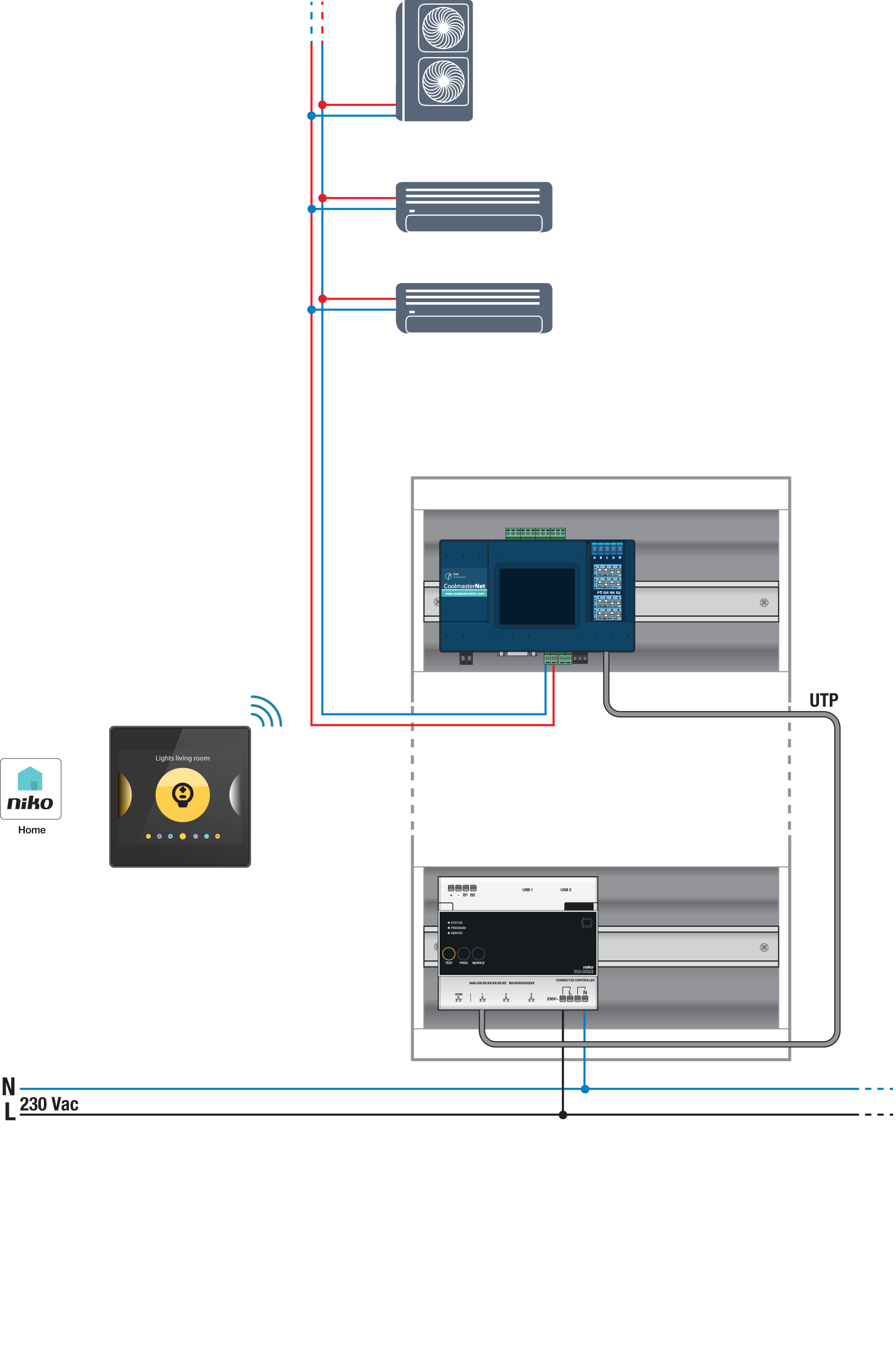
Systemoversigt
For at undgå krydstale i nye installationer, skal du tilslutte alle SELV-kabler til venstre på el-tavlen og alle højspændingsledninger til højre på el-tavlen. Grupper alle lavspændingsmoduler sammen.
CoolMaster skal tilsluttes på LAN porten på controlleren for at muliggøre kommunikation med Niko Home Control installationen.
CoolMaster tilsluttes på HVAC-enhederne med en kabeltilslutning.
CoolMaster komponenter
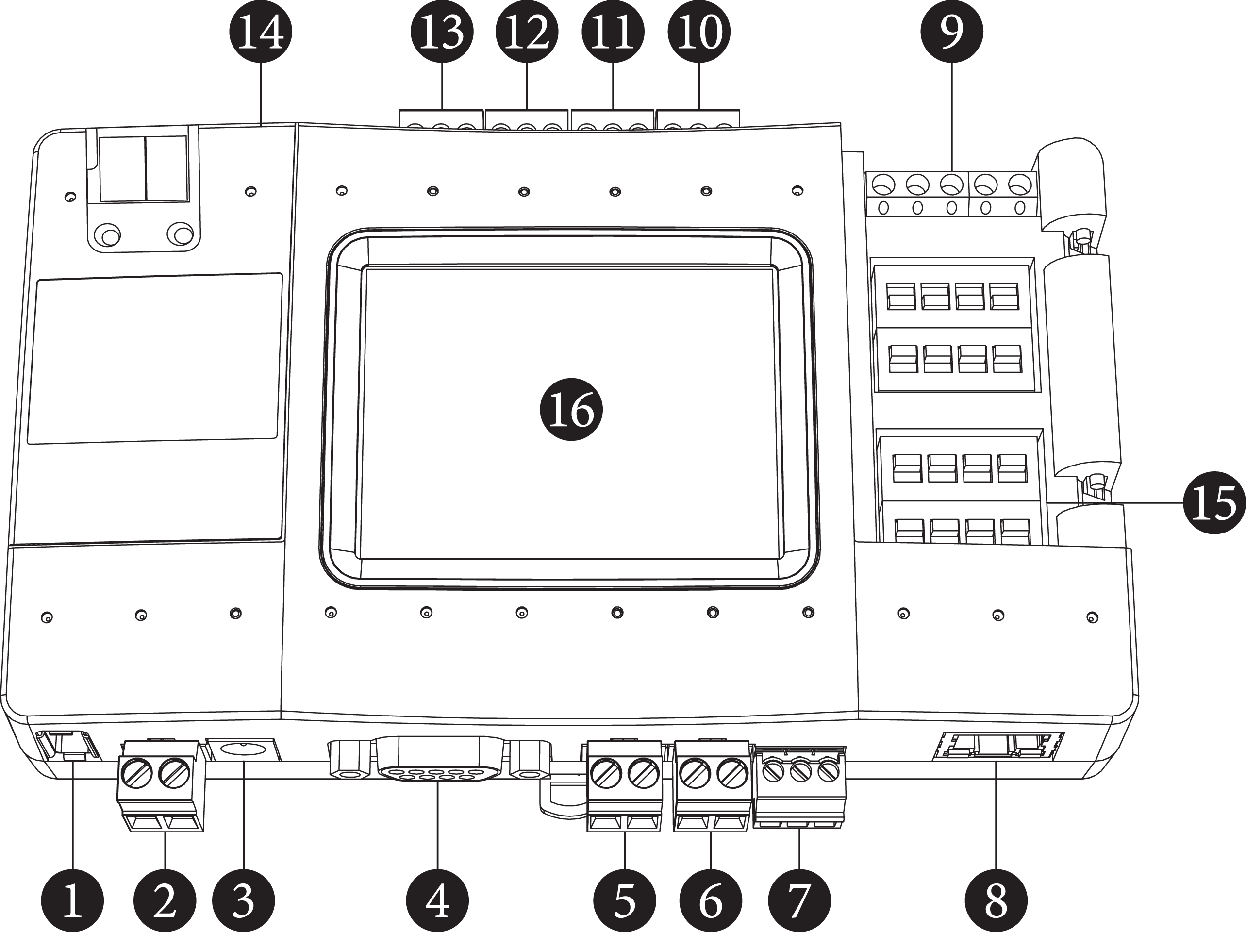
L8 - HVAC Linje 8 (USB vært)
Strøm
Strømstik
RS232 port
L1 - HVAC Linje 1
L2 - HVAC Linje 2
L3 - RS485
Ethernet port
GPIO'er
L7 - HVAC Linje 7
L6 - HVAC Linje 6
L5 - HVAC Linje 5
L4 - HVAC Linje 4
USB enhedsport
DIP switches P, Q, R, S
LCD Touchskærm
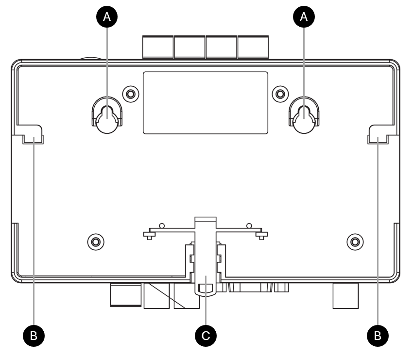
1. Montering af CoolMaster
Monter CoolMasteren på en af følgende måder:
På en væg: Fastgør skruerne til væggen ved placeringen af monteringshullerne (A). Afstanden mellem midtpunkterne er 79 mm.
På DIN-skinnen: Placer monteringsfødderne (B) på DIN-skinnen, skub den nederste del af enheden på DIN-skinnen for at låse den på plads. For at afmontere skal du trække monteringslåsen (C) i bunden af enheden ned.
2. Tilslutning af CoolMasteren
550-00550 (HVAC universalinterface) leveres med en standard konfiguration til Daikin VRV. Når du anvender en anden HVAC, skal interfacet konfigureres i overensstemmelse hermed (DIP-switch indstilling, og HVAC-linje indstilling via displayet).
For at tilslutte HVAC interfacet til et VRV- eller VRF-klimaanlæg skal du tilslutte et to-leder HVAC-buskabel mellem terminalerne til den/de indendørs enhed (er) og tilslutningen på CoolMaster (med det medfølgende interface stik).
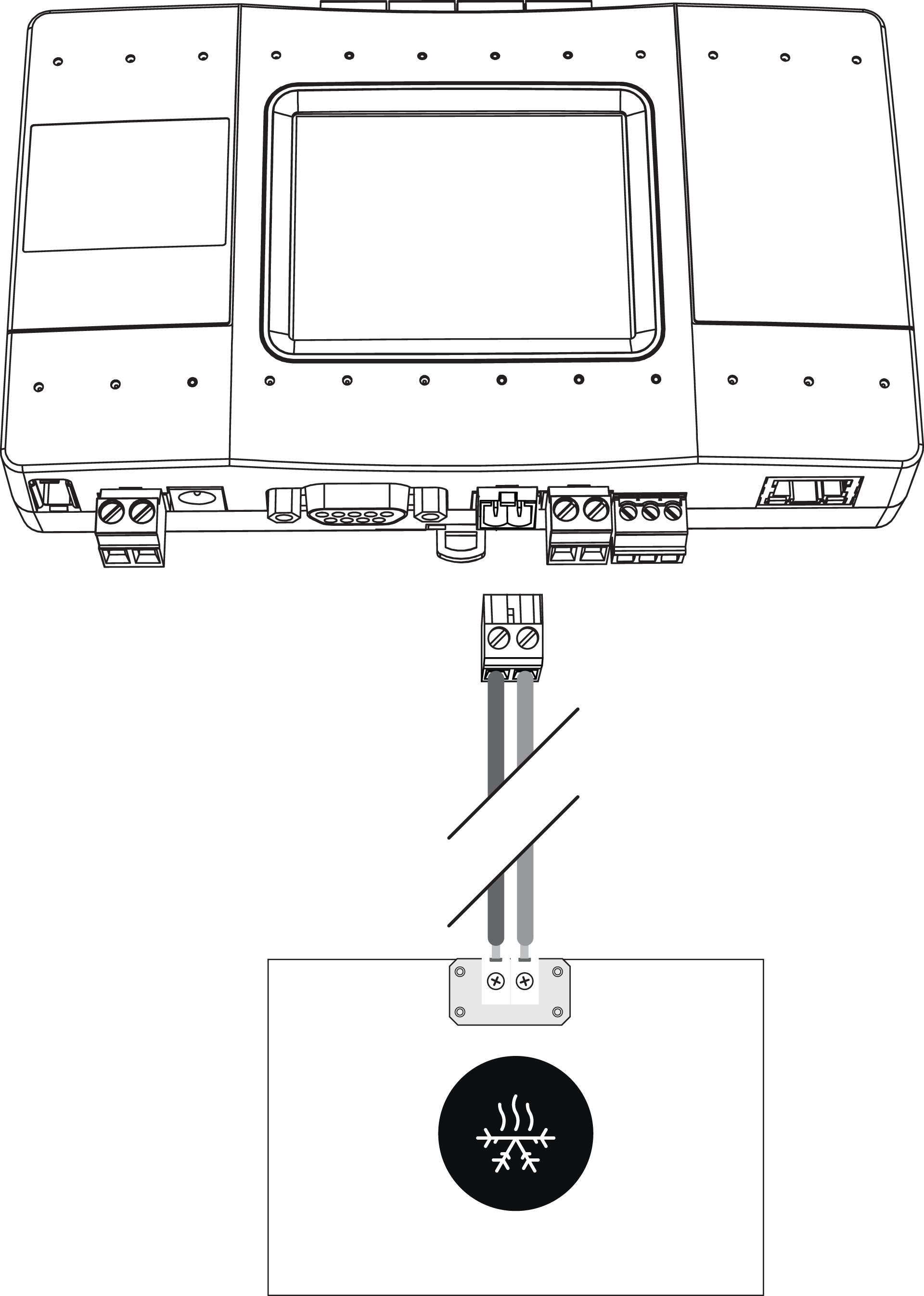
Tabellen nedenfor giver en oversigt over tilslutningsklemmerne på de(n) indendørs enhed(er) for hver type HVAC-system og den tilsvarende tilslutning på CoolMaster:
HVAC-system | Tilslutningsklemmer på indendørs enhed | Polaritet | Tilslutninger på HVAC interface (CoolMaster) | Skærmet netværkskabel |
|---|---|---|---|---|
Daikin* | F1 F2 | Ingen | L1 eller L2 | Ikke påkrævet |
Panasonic/Sanyo | U1 U2 | Ingen | Obligatorisk | |
Toshiba | U1 U2 | Ingen | Obligatorisk | |
Mitsubishi Electric | M1 M2 | Ingen | Obligatorisk | |
Hitachi | 1 2 (på udendørs enhed) | Ingen | Obligatorisk | |
Haier | P Q (på udendørs enhed) | Ingen | Obligatorisk | |
LG | Inter A, Inter B (på udendørs enhed) | + - | L3, L4, L5, L6 eller L7 | Obligatorisk |
Gree/GMV4 VRF | G1 G2 | + - | Obligatorisk | |
Gree/GMV5, GMV6 VRF | G1 G2 (på udendørs enhed) | + - | L8 | Obligatorisk |
Mitsubishi Heavy Industries | A B (på udendørs enhed) | + - | L3, L4, L5, L6 eller L7 | Obligatorisk |
Samsung | F1 F2 eller R1 R2 (på udendørs enhed) | + - | Obligatorisk | |
Midea | X Y E (på udendørs enhed) | + - GND | Obligatorisk | |
Trane | X Y E (på udendørs enhed) | + - GND | Obligatorisk | |
Chigo | X Y E (på udendørs enhed) | + - GND | Obligatorisk | |
Blue Star | A2 B2 (på udendørs enhed) | + - | Obligatorisk | |
Fujitsu | Z1 Z2 (på udendørs enhed) | Ingen | L8 | Obligatorisk |
AUX | A B (på udendørs enhed) | + - | L7 | Obligatorisk |
Tica | A2 B2 (på udendørs enhed) | + - | Obligatorisk |
*Det er nødvendigt at konfigurere en central (gruppe) adresse i Daikin systemet.
Når du tilslutter HVAC-enheder af flere mærker, skal du tage højde for følgende begrænsninger:
Når DIP switchene P1 og P2 er "ON", kan linjerne L6 og L7 ikke anvendes som separate linjer. I dette tilfælde vil polariteten på HVAC-kablet, der er tilsluttet L7, automatisk blive registreret.
Linje L2 kan ikke tilsluttes samtidigt med linje L6 og linje L1 kan ikke tilsluttes samtidigt med linje L5
3. Dip switch indstillinger
Åbn klappen øverst i højre side af HVAC interfacen og kontroller at dip kontakterne står korrekt i henhold til tabellen nedenfor.
DIP Switch P
Afbryder | TÆNDT | SLUKKET |
|---|---|---|
P1 og P2 | Forbind L6, L7 og aktiver automatisk polaritetsdetektion på L7 | Adskil L6, L7 |
P3 | L6 aktiveret, L2 deaktiveret | L2 aktiveret, L6 deaktiveret |
P4 | Ikke relevant | Normal driftsfunktion |
P1 og P2 skal være i samme position.
DIP Switch Q og R
DIP switch Q og R bruges til at justere de interne parametre for HVAC-ledningerne L1 og L2.
HVAC-system | Q1 | Q2 | Q3 | Q4 |
|---|---|---|---|---|
Daikin | TÆNDT | SLUKKET | TÆNDT | SLUKKET |
Mitsubishi Electric | SLUKKET | SLUKKET | SLUKKET | SLUKKET |
Toshiba | SLUKKET | TÆNDT | SLUKKET | TÆNDT |
Panasonic/Sanyo | SLUKKET | TÆNDT | SLUKKET | TÆNDT |
Hitachi | SLUKKET | TÆNDT | SLUKKET | TÆNDT |
Haier | SLUKKET | TÆNDT | SLUKKET | TÆNDT |
HVAC-system | R1 | R2 | R3 | R4 |
|---|---|---|---|---|
Daikin | TÆNDT | SLUKKET | TÆNDT | SLUKKET |
Mitsubishi Electric | SLUKKET | SLUKKET | SLUKKET | SLUKKET |
Toshiba | SLUKKET | TÆNDT | SLUKKET | TÆNDT |
Panasonic/Sanyo | SLUKKET | TÆNDT | SLUKKET | TÆNDT |
Hitachi | SLUKKET | TÆNDT | SLUKKET | TÆNDT |
Haier | SLUKKET | TÆNDT | SLUKKET | TÆNDT |
Hvis alle DIP switche R1, R2, R3 og R4 er i position ON under en nulstilling af strømmen, tvinges CoolMaster til BOOT funktion.
DIP kontakt S
Afbryder | TÆNDT | SLUKKET |
|---|---|---|
S1 og S2 | Aktiver DC udgang på HVAC-linje L1 | Deaktiver DC udgangd på HVAC-linje L1 |
S3 og S4 | Aktiver DC udgang på HVAC-linje L2 | Deaktiver DC udgang på HVAC-linje L2 |
S1 og S2 skal være i samme position.
S3 og S4 skal være i samme position.
Disse indstillinger gælder kun, hvis du skal tilslutte HVAC interfacet til et ikke-VRF-system via en KRP- eller MAC-adapter, og ingen anden DC kilde er til stede på denne linje.
4. Tænding af CoolMaster
Tænd CoolMasteren på en af følgende måder:
Tilslut strømadapteren (medfølger) på HVAC interfacet og tilslut adapteren på lysnettet.
Tilslut direkte på strømforsyningen fra den lokale el-tavle.
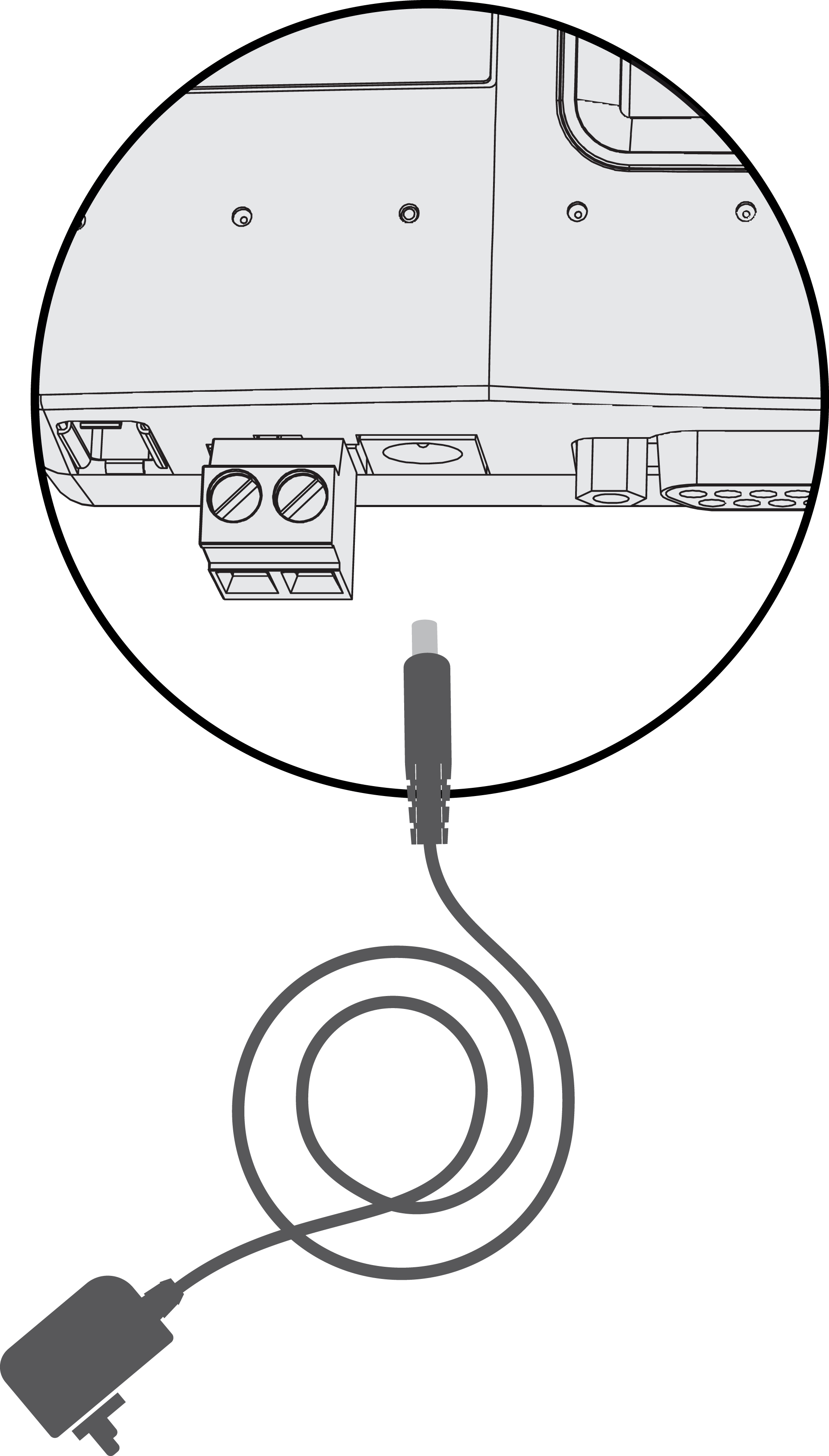 | 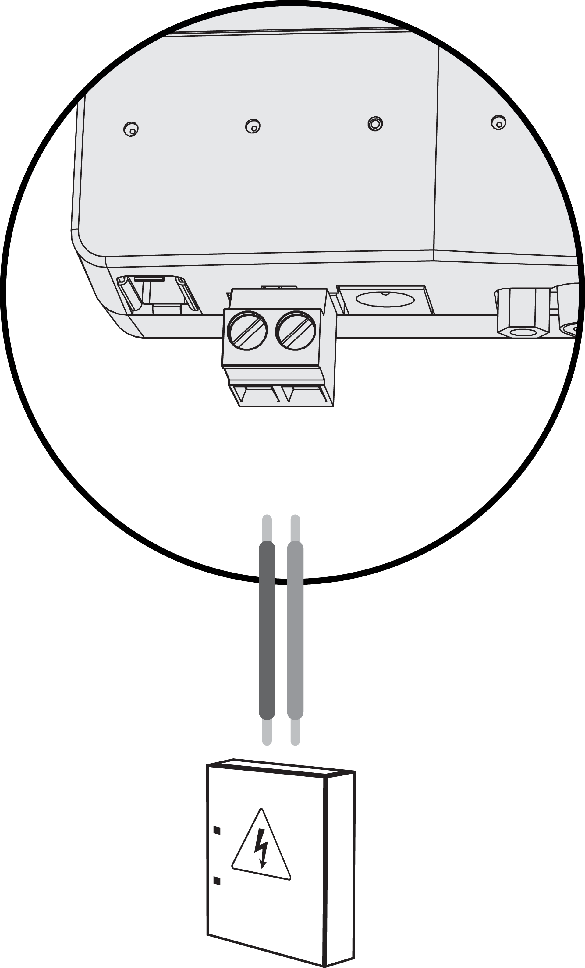 |
Indgangsspænding: 12V DC | Indgangsspænding: 12 - 24V DC |
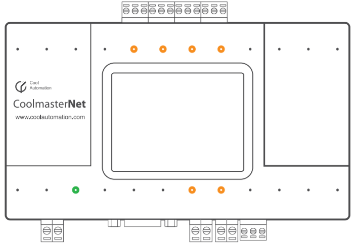
Displayet og den grønne LED vil lyse.
5. HVAC-linje indstillinger
Forkortelse | HVAC-system |
|---|---|
DK | Daikin |
HT | Hitachi |
HA | Haier |
ME | Mitsubishi Electric |
TO | Toshiba |
PN | Panasonic |
FJ | Fujitsu |
LG | LG |
SM | Samsung |
MD | Midea |
CG | Chigo |
GR | Gree |
AU | AUX |
BS | Blue Star |
MH | Mitsubishi Heavy Industries |
Vælg på displayet det korrekte mærke af HVAC-systemet for den anvendte linje.
Gå til Indstillinger.

Gå til HVAC linje.

Vælg den HVAC linje, du vil konfigurere.

Konfigurer HVAC-linjetypen.

LED-programmering
 | Grøn LED lyser konstant | God forbindelse |
 | Orange LED blinker | Dataoverførsel:
|
Fejlfinding
Problem | Mulig årsag | Løsning |
|---|---|---|
Ingen information vises på displayet | Fejl i strømforsyningen | Kontrollér, at der er et stabilt signal fra 9V DC adapteren |
Antallet af indendørs enheder der vises på displayet, er ikke korrekt | Det kan tage nogle minutter før HVAC systemet er genkendt. Der er et problem med kommunikationen til HVAC systemet. |
|
