Description
The HVAC Universal Interface allows you to connect a VRV, VRF or multi-split air conditioning system (HVAC system) to the Niko Home Control installation. This module acts as the interface between the air conditioning system and the Niko Home Control gateway and allows communication between both devices.
Overview

Order numbers
550-00550: HVAC universal interface for Daikin VRV, Sanyo (Panasonic) VRF, Toshiba VRF, Mitsubishi Electric VRF, LG VRF, Fujitsu (Atlantic) VRF, Mitsubishi Heavy VRF, Hitachi VRF
The following order numbers are replaced by 550-00550 (HVAC universal interface):
550-00551: HVAC interface for Daikin VRV
550-00552: HVAC interface for Sanyo (Panasonic) VRF
550-00553: HVAC interface for Toshiba VRF
550-00554: HVAC interface for Mitsubishi Electric VRF
550-00556: HVAC interface for LG VRF
550-00557: HVAC interface for Fujitsu (Atlantic) VRF
550-00558: HVAC interface for Mitsubishi Heavy VRF
550-00559: HVAC interface for Hitachi VRF
The 550-00550 (HVAC universal interface) comes with a default configuration for Daikin VRV. When using another HVAC, the interface needs to be configured accordingly (DIP switch setting, and HVAC line via its display).
Operation
The HVAC interface allows you to control an HVAC system using a Niko Home Control HVAC thermostat. See Push buttons with display.
Only one HVAC interface is needed for the different HVAC systems. Only one HVAC interface can be connected to an HVAC system. To connect a multi-split air conditioning system, you will need an additional module in each indoor unit.
- It is not possible to combine different brands of air conditioning systems into one Niko Home Control installation.
- It is not possible to connect an additional heating element to the HVAC thermostat.
- The HVAC interface synchronizes the Niko Home Control installation and the HVAC system every 10 minutes and after every action from the installation. The parameters that will be synchronized are heating/cooling, on/off, ventilation speed, desired temperature and temperature settings.
- A maximum of 20 HVAC thermostats can be connected to the Niko Home Control installation. This means you can create up to 20 zones.
- The Niko Home Control installation can control a maximum of 8 indoor units per zone/HVAC thermostat.
- The HVAC interface can interact with a maximum of 32 indoor units.
- The HVAC system has its own order of priority when responding to various commands from different zones.
Installation
Connection diagrams
- To avoid crosstalk in new installations, connect all SELV cables to the left inside the electrical cabinet and all high-voltage cables to the right inside the electrical cabinet.
- Group all low-voltage modules together, such as the Nikobus interface or the Easywave RF interface, to ensure that the Nikobus cable or the antenna can run alongside the SELV cable.

Connecting and mounting the HVAC interface
- Preferably, use an HVAC system that is galvanically isolated from the mains.
- Do not connect more than one HVAC interface to the Niko Home Control installation.
- The resident must ensure that the Wi-Fi network is secure. This protection is necessary for using the app on a smartphone or tablet.
- Connecting the HVAC interface to a VRV or VRF air conditioning system or a multi-split air conditioning system:
To connect the HVAC interface to a VRV or VRF air conditioning system, connect the HVAC interface via a two-wire HVAC bus cable to the indoor unit(s). The following table provides an overview of the bus connection to the indoor unit(s) for each type of HVAC system:
HVAC System Communication network Bus connection Polarity No. of indoor units No. of outdoor units Shielded network cable Daikin D3 Net F1 F2 None 64 10 Not required Toshiba TCC Link U1 U2 None 64 10 Required Sanyo (Panasonic) S3 Net U1 U2 None 64 10 Required Mitsubishi Electric M-Net(TB3,TB7) M1 M2 None 50 10 Required Fuijitsu (Atlantic) VRF transmission line X1 X2 None 64 10 Required Mitsubischi Heavy Super Link New Super Link A B None 128 10 Required Hitachi H Link, H Link 2 1 2 None 64 10 Required LG Inter A, Inter B (only outdoor) None 128 10 Required The HVAC interface is equipped with a USB port and seven connections: L1 – L7. Five of these seven connections can
be controlled simultaneously, but L2 and L6 cannot because they share the same electronics. The next table gives an
overview of which connection on the HVAC interface must be used for which system.HVAC Manufacturer Abbreviation USB L1 L2 L3 L4 L5 L6 L7 Daikin DK Misubishi Electric ME Sanyo (Panasonic) SA Toshiba TO Hitachi HT Fuijistu (Atlantic) LG LG Mitsubishi Heavy Industries MH Gree GR
- To connect the HVAC interface with a multi-split air conditioning system, you must first connect an additional module (PCB connection) for each indoor unit. The HVAC interface cannot be connected directly to the indoor unit(s) of a multi-split air conditioning system. The supplier of the HVAC system should supply these additional module(s) to be connected to the two-wire HVAC bus cable.
- Open the flap on the top right-hand side of the HVAC interface and check to ensure the dip switches are set as follows.

DIP Switch P
Switch On Off P3 L6 active, L2 inactive L2 active, L6 inactive P4 production mode normal operating mode DIP Switch Q
HVAC type DIP switch Q - HVAC line L1 Q1 Q2 Q3 Q4 DK ON OFF ON OFF ME OFF OFF OFF OFF TO OFF ON OFF ON SA OFF ON OFF ON
DIP Switch R
HVAC type DIP Switch R - HVAC line L2 R1 R2 R3 R4 DK ON OFF ON OFF ME OFF OFF OFF OFF TO OFF ON OFF ON SA OFF ON OFF ON If all DIP switches R1, R2, R3 and R4 are placed in the ON position, the HVAC interface goes into BOOT mode.DIP Switch S
Switch ON OFF S1, S2 turn on DC output on HVAC line L1 turn off DC output on HVAC line L1 S3, S4 turn off DC output on HVAC line L2 turn off DC output on HVAC line L2 Switch S1 should always be in the same position as S2; switch S3 in the same position as S4.
These settings are only applicable if you need to connect the HVAC interface to a non-VRF system via a KRP or MAC adapter.
3. Press the HVAC interface anywhere onto the DIN rail until it clicks into place.
4. Connect the bus of the HVAC system to the green interface connector (included). Click the green interface connector at the bottom/top on the HVAC interface on line L1, L2, L3, L4, L5, L6 or L7, depending on the type of indoor unit that is used.

5. Connect the network cable to the LAN part of the connected controller.

6. Connect the power adapter to the HVAC interface and connect the adapter to the mains.
The display and the green LED will light up.
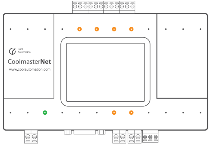
The orange LEDs blink:
- during data transfer from the HVAC thermostat to the HVAC interface
- only if line L1, L2, L3, L4, L5, L6, L7 is connected to an indoor unit.
| LED | colour | status | status |
|---|---|---|---|
| connection | green | on off | good connection no connection |
| activity | orange | blinking | data transfer |
7. Select the correct brand of HVAC system on the HVAC interface for the used line. Make sure the dip switches are set properly for the brand (see step 2).
- Go to Settings.

- Go to HVAC line.

- Select the HVAC line you want to configure.

- Configure the HVAC line type.

Information on the display
When there is communication with the HVAC system, the display provides extra information about the installation. Below,
you can see an example of this type of display. The values shown in the example are only indicative and could differ from
actual values.
Information shown on the display with the status of the indoor units:


Information shown on the display with the number of indoor units and zones:

| Value displayed | Symbol | Value in the example display |
|---|---|---|
| No. of recognised indoor units | U | 10 |
| No. of groups | G | 8 |
| Error code | A3 | |
| Error code | U4 |
Troubleshooting
| Problem | Possible cause | Solution |
|---|---|---|
No information appears on the display | Malfunctioning power supply | Verify that there is a steady signal from the 9V DC power adapter |
The number of indoor units displayed on the display is not correct | It may take a few minutes before the HVAC system is recognised. There is a problem with communication to the HVAC system. |
|
Technical data
- power supply voltage: 9 – 24 Vdc
- installation method: wall mounting or DIN rail mounting
- operating conditions:
- ambient temperature: 0 - 45°C
- humidity: less than 85 % RV
- dimensions: 90 x 155 x 33 mm (H x W x D)
- weight: 270 g
- maximum number of indoor and outdoor units: depends on the manufacturer
- CE marked