What do you need?
Niko requirements
Din Niko Home Control-installation opfylder følgende krav:
-
Den har en trådløs smart hub eller en controller II.
-
Den er konfigureret med den seneste programmeringssoftware.
Afhængigt af grundmodulerne i din Niko Home Control installation skal du installere følgende ekstra produkter:
|
|
Påkrævede ekstra produkter |
Referencenumre |
|---|---|---|
|
Controller |
Digitalt potentialfrit sensormodul med en fri indgang pr. signal du vil bruge i Niko Home Control Hvis udgangskontakten på din tredjepartsenhed ikke er potentialfri, har du brug for et ekstra potentialfrit kontaktmodul (fx Finder 22.32.0.230.1xx0 til 230 V tilslutninger, Finder 22.32.0.012.1xx0 til 12 V DC tilslutning, Finder 22.32.0.024.1xx0 til 24 V DC tilslutninger) |
|
|
Controller med en trådløs bridge |
Smart (dobbelt) afbryder med én ledig indgang (E) pr. signal, som du vil bruge i Niko Home Control Hvis udgangskontakten på din tredjepartsenhed ikke er 230 V, har du brug for et ekstra 230 V kontaktmodul (fx Finder 22.32.0.230.1xx0 til potentialfri tilslutninger, Finder 22.32.0.012.1xx0 til 12 V DC tilslutning, Finder 22.32.0.024.1xx0 til 24 V DC tilslutninger) Den smarte (dobbelt) afbryder kan placeres på en DIN-skinne ved hjælp af en modulær holder (fx. Legrand 412950) |
|
|
Trådløs smart hub |
Smart (dobbelt) afbryder med én ledig indgang (E) pr. signal, som du vil bruge i Niko Home Control Hvis udgangskontakten på din tredjepartsenhed ikke er 230 V, har du brug for et ekstra 230 V kontaktmodul (fx Finder 22.32.0.230.1xx0 til potentialfri tilslutninger, Finder 22.32.0.012.1xx0 til 12 V DC tilslutning, Finder 22.32.0.024.1xx0 til 24 V DC tilslutninger) Den smarte (dobbelt) afbryder kan placeres på en DIN-skinne ved hjælp af en modulær holder (fx. Legrand 412950) |
Third party system requirements
Dit system opfylder følgende krav:
-
Dit alarmsystem har en potentialfri eller 12/24 V DC eller 230 V AC udgangskontakt, der giver signal, når alarmen går.
-
Det er kompatibelt med Niko modulet (se Nikos krav).
Wiring diagrams
If you also want to receive a signal when the alarm is (dis)armed, you need to connect additional contacts, see General solution: Automation based on state of security alarm.
Connecting the sensor module
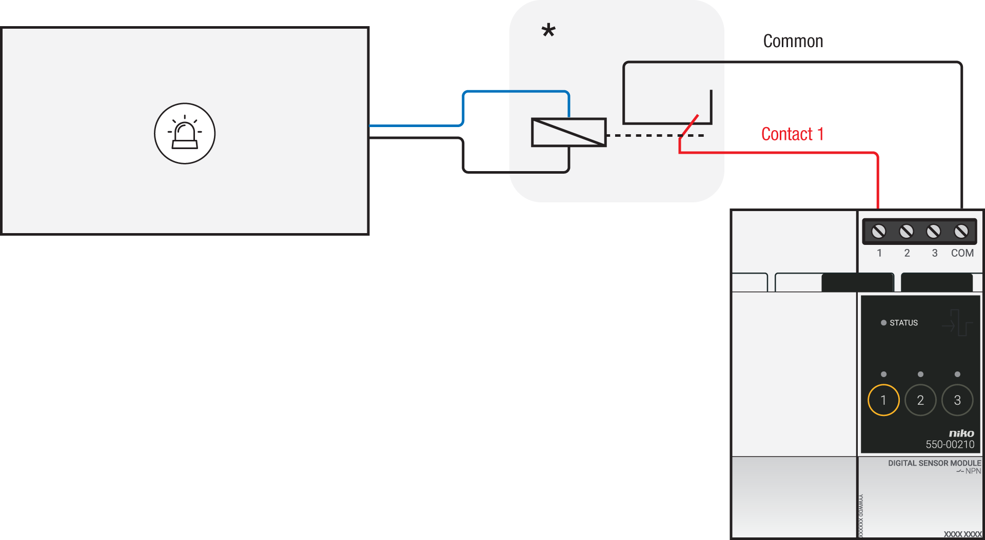
Via potential-free output contact
Connect contact 1 on the Niko sensor module to the output on the third-party system, as shown in the wiring diagram.

Via 230 V or 12/24 V output contact
If the contacts of your alarm system are not potential-free, you additionally need an appropriate potential-free contact module.
Connect contact 1 on the Niko sensor module to the output on the third-party system, as shown in the wiring diagram.
|
230 V output contact |
12/24 V output contact |
|---|---|
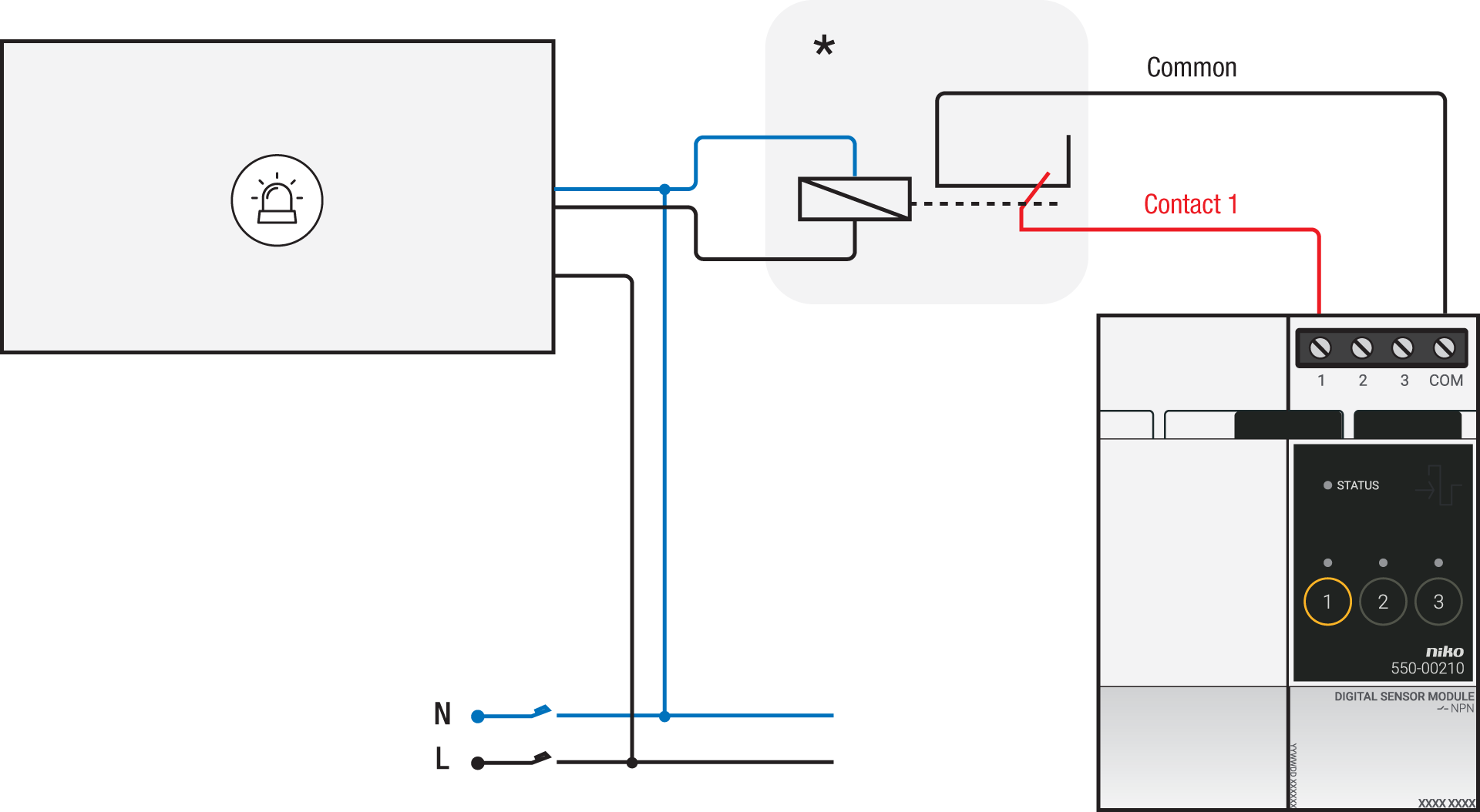
*230 V to potential-free contact module (e.g. Finder 22.32.0.230.1xx0) |
*12 V to potential-free contact module (e.g. Finder 22.32.0.012.1xx0) or 24 V to potential-free contact module (e.g. Finder 22.32.0.024.1xx0) |
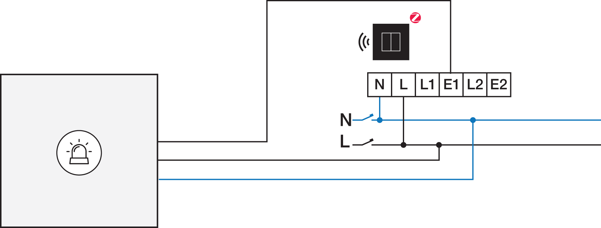
Connecting the connected switch
Via potential-free output contact
If the contacts of your alarm system are not 230 V, you additionally need an appropriate potential-free contact module.
Connect contact 1 on the Niko connected switch to the output on the third-party system, as shown in the wiring diagram.

*230 V to potential-free contact module (e.g. Finder 22.32.0.230.1xx0)
Via 230 V or 12/24 V output contact
If the contacts of your alarm system are not 230 V, you additionally need an appropriate contact module.
Connect contact 1 on the Niko connected switch to the output on the third-party system, as shown in the wiring diagram.
|
230 V output contact |
12/24 V output contact |
|---|---|
|
*12 V to 230 V contact module (e.g. Finder 22.32.0.012.1xx0) or 24 V to 230 V contact module (e.g. Finder 22.32.0.024.1xx0) |